7.1.5 LIFT CYLINDER
The two lift cylinders of single-acting type are located on the outer mast frame. Each lift
cylinder, consists of cylinder body, rod, piston, and cylinder cap.
The piston fastened to the rod with a snap ring is provided with a wear ring and packing on its
circumference.
At this lower part of the cylinder body provided is a cut-off valve which works as a safety
device when the high-pressure hose connecting the right and left lift cylinders is broken.
The bushing and oil seal pressed into the cylinder cap serve to support the rod and protect the
inside of the cylinder from dust.
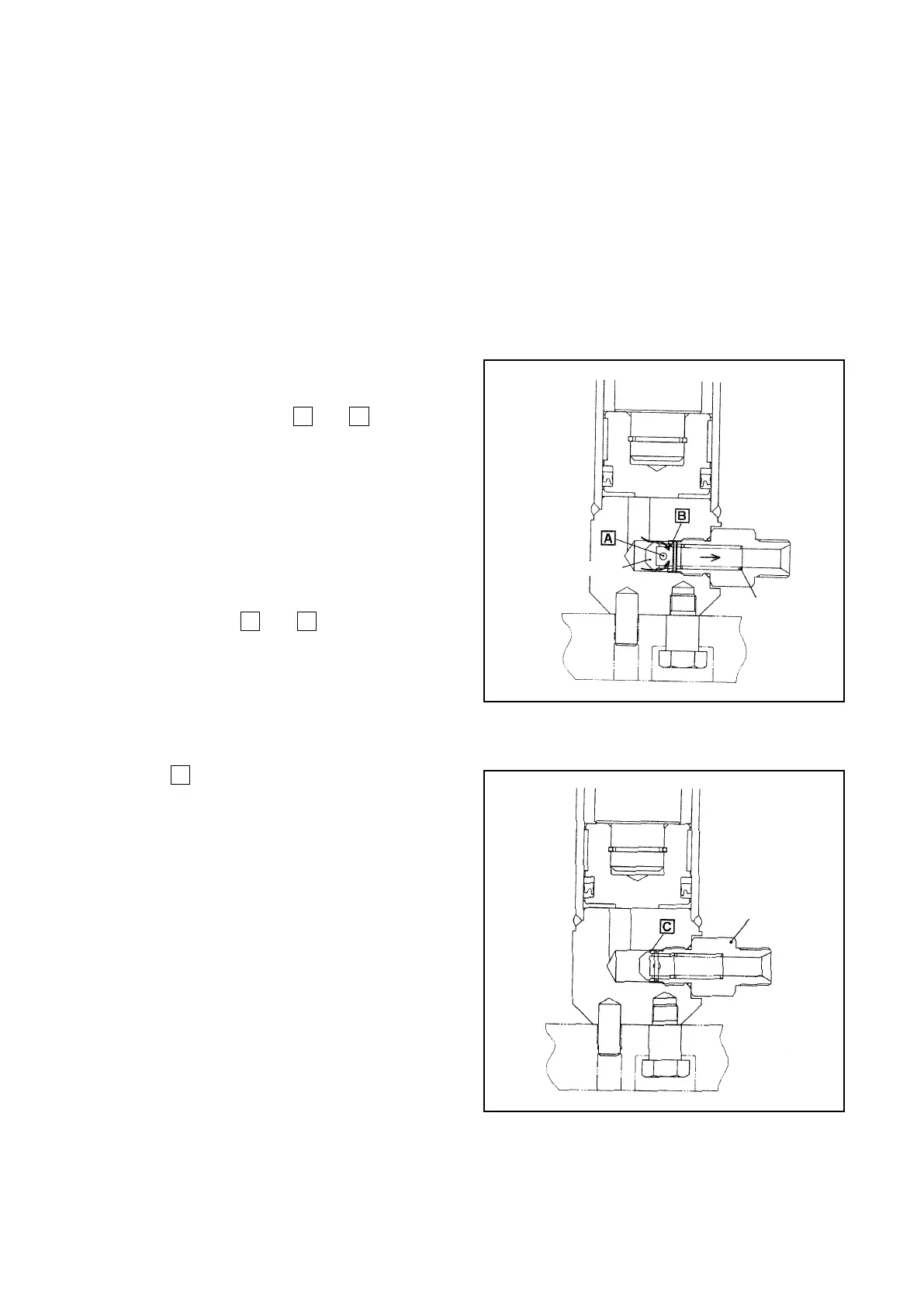
■ Cut-off valve operation
The oil from the cylinder flows back to the
tank via the piston holes
A
and
B
. In this step,
if the flow rate passing through the holes are
within a range of the flow rate which can be
controlled by the flow regulator, the pressure
difference between the front and rear of the
piston is less than the spring force so that the
piston does not move.
If the hose is ruptured and the oil passing
through the holes
A
and
B
exceeds the ow to
be controlled, the pressure difference between
the front and rear of the piston becomes larger
than the spring force, moving the piston to the
right.
The piston is thereby in firm contact the
section
C
of the case so that the oil in the
cylinder does not ow out, stopping the fork go
down.
Fig. 7.6 In Below Control Flow Rate
SPRING
PISTON
Fig. 7.7 In Over Control Flow Rate
CASE