Ԙ
ԙ
Ԛ
ԛ
Ԝ
ԝ
Ԟ
ԟ
Ԡ
ԡ
Ԣ
ԣ
Ԥ
ԥ
Ԧ
ԫ
Ԩ
B
21
22
23
24
25
26
27
ԧ
ԩ
Ԫ
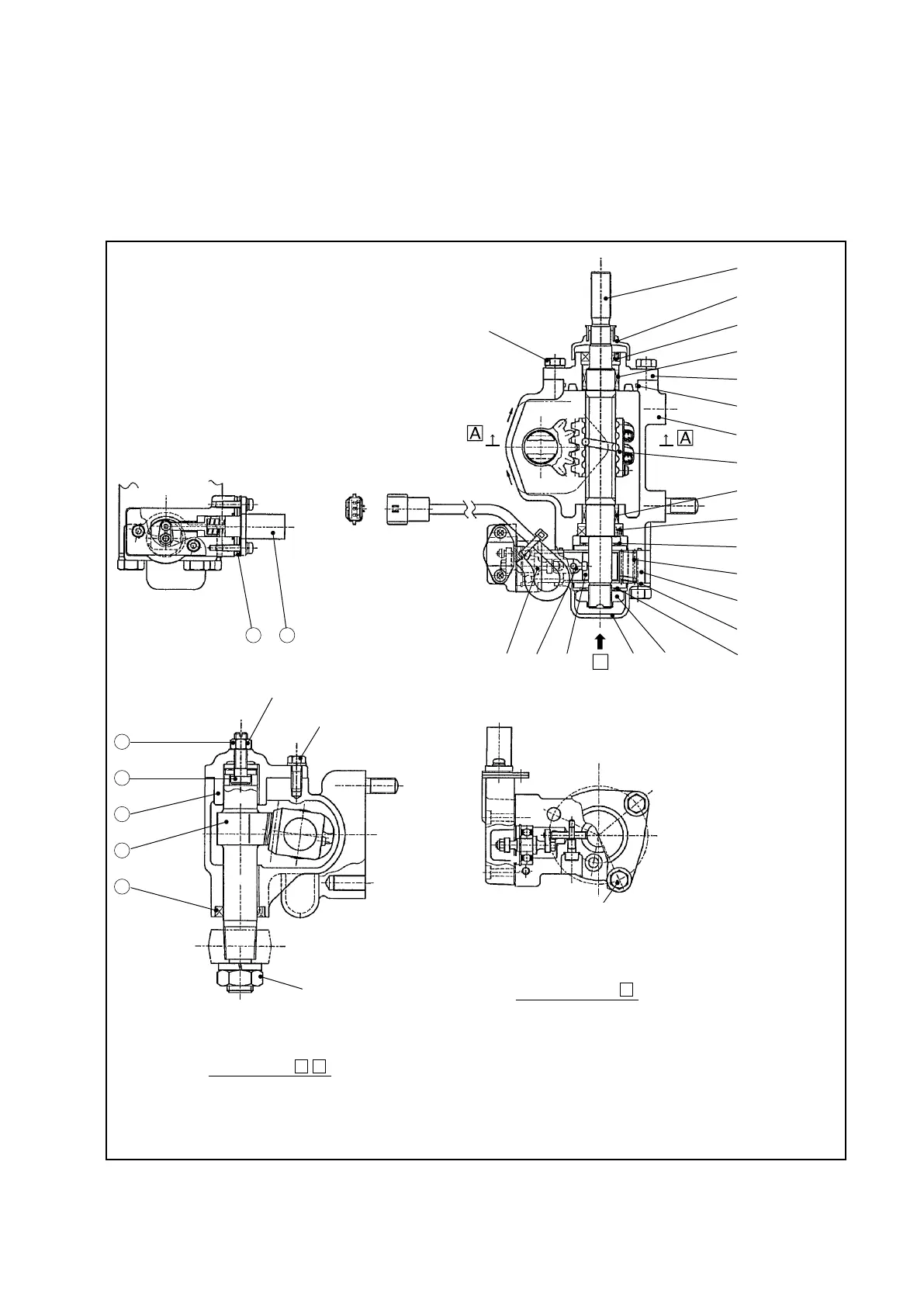
Fig. 6B.2 Steering Gearbox
6B.1.2 STEERING GEARBOX
The steering gearbox is constructed as shown in Figure 6B.2. Rotation of the steering wheel
is transmitted to the sector shaft by way of the ball nut screw. At the lower part of the steering
gearbox unit is located the potentiometer which converts slight up-and-down movement of the
steering shaft into a voltage and sends the voltage to the controller.
1. SHAFT
2. DUST COVER
3. OIL SEAL
4. NEEDLE BEARING
5. REAR COVER
6. “O”-RING
7. GEARBOX
8. BALL NUT
9. NEEDLE BEARING
10. OIL SEAL
11. THRUST BEARING
12. SPRING
13. SENSOR HOUSING
14. “O”-RING
15. THRUST BEARING
16. LOCK NUT
17. FRONT COVER
18. SLIDE RING
19. ARM
20. ROLLER
21. POTENTIOMETER
22. SHIMS
23. LOCK NUT
24. ADJUSTMENT SCREW
25. SIDE COVER
26. SECTOR SHAFT
27. OIL SEAL
Tightening torque:
16.7 to 27.5 N-m
{170 to 280 kgf-cm}
[147.8 to 243.4 lbf-in.]
Tightening torque:
19.6 to 29.4 N-m {200 to 300 kg-cm}
[173.5 to 260.2 lbf-in.]
Tightening torque:
16.7 to 27.5 N-m
{170 to 280 kgf-cm}
[147.8 to 243.4 lbf-in.]
View looking from
B
Sectional view
A
-
A
Tightening torque: 37.3 to 53 N-m
{380 to 540 kgf-cm}
[330.1 to 469.1 lbf-in.]
Tightening torque:
140 to 170 N-m
{1427.6 to 1733.5 kgf-cm}
[1239.1 to 1504.6 lbf-in.]
6B. STEERING SYSTEM (EPS type)