Circuit Diagram Description
Drive System
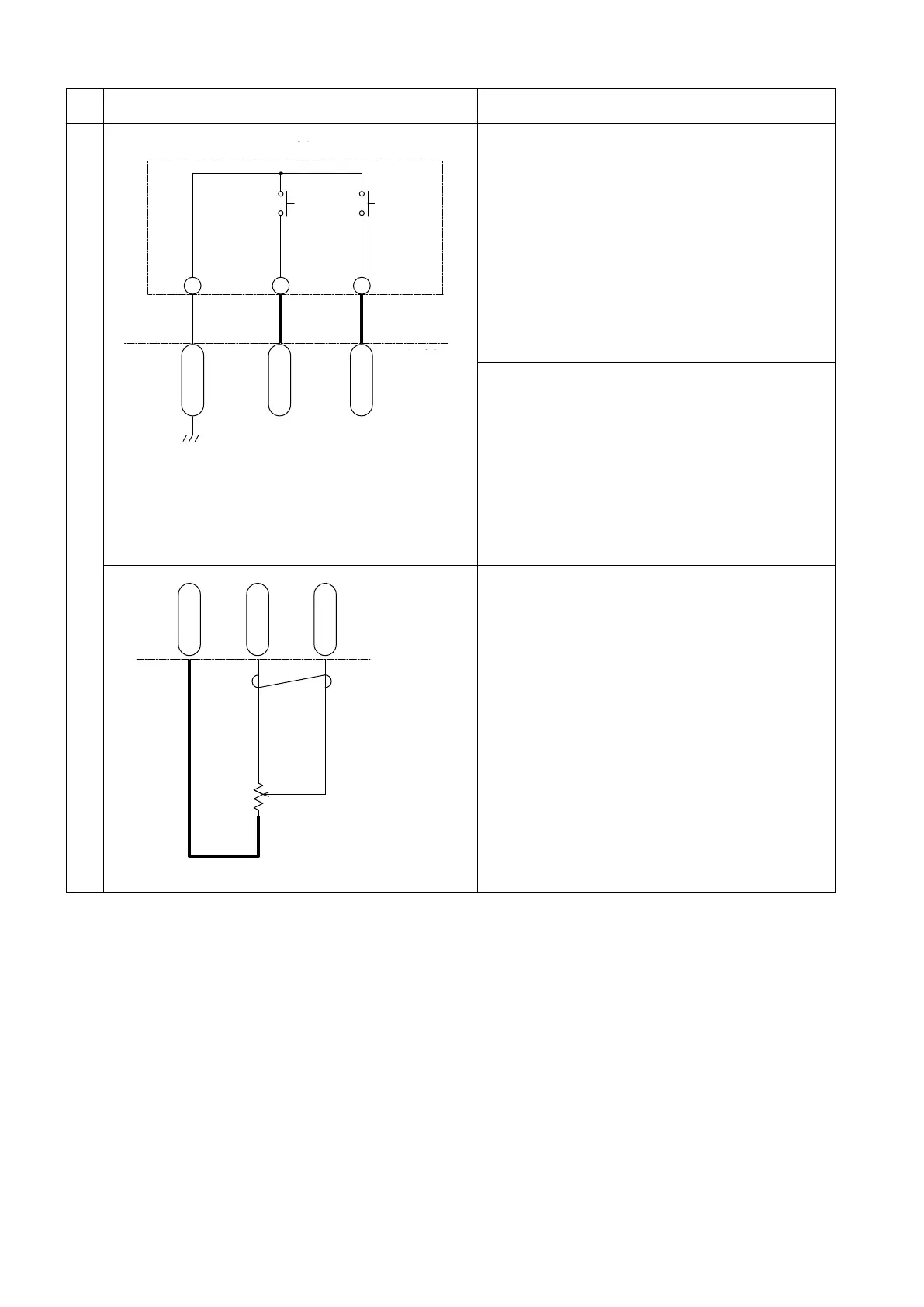
CN9-1-8
CN9-1-15
CN9-1-16
COM
S4
Gy 80
W 77
WL 75
スイッチパネル
S5
メータパネル
スピード
コントロール
スイッチ
S.P.E
セレクト
スイッチ
10. Speed control switch (“turtle” button)
(1) When speed control switch is pressed, the
turtle mark appears on the LCD panel,
activating travel speed limit feature. If the
speed control switch is pressed with the
turtle mark appeared on the LCD panel,
travel speed limit feature is cancelled.
(2) Voltage between CN9-1-16 and CN9-1-8
terminals
Speed control switch pressed: 0 V
Speed control switch released: 5 V
11. S.P.E mode selection switch
(1) Acceleration speed and top speed can
be switched over in 3 stages. The speed
control mode changes in turns from S, P, to
E every time the switch is pressed.
(2) Voltage between CN9-1-15 and CN9-1-8
terminals
S.P.E selection switch pressed: 0 V
S.P.E selection switch released: 5 V
走行コントローラ
CN2D-34
CN2D-23
CN2D-10
-
+
YL 43
YR 44
YB 42
12. Steering potentiometer
(1) Potentiometer power supply
4.8V is supplied from the CN2D-34
terminal.
(2) Voltage between CN2D-10 and CN2D-23
terminals
The voltage at the CN2D-10 terminal
varies according to the steering angle of the
wheels.
Steering angle at neutral: 2.5 V
Steering angle at left end: 3.5 V
Steering angle at right end: 1.8 V
Switch panel
S.P.E
selection
switch
Speed
control
switch
LCD panel
Drive motor inverter unit