Circuit Diagram Description
Drive System
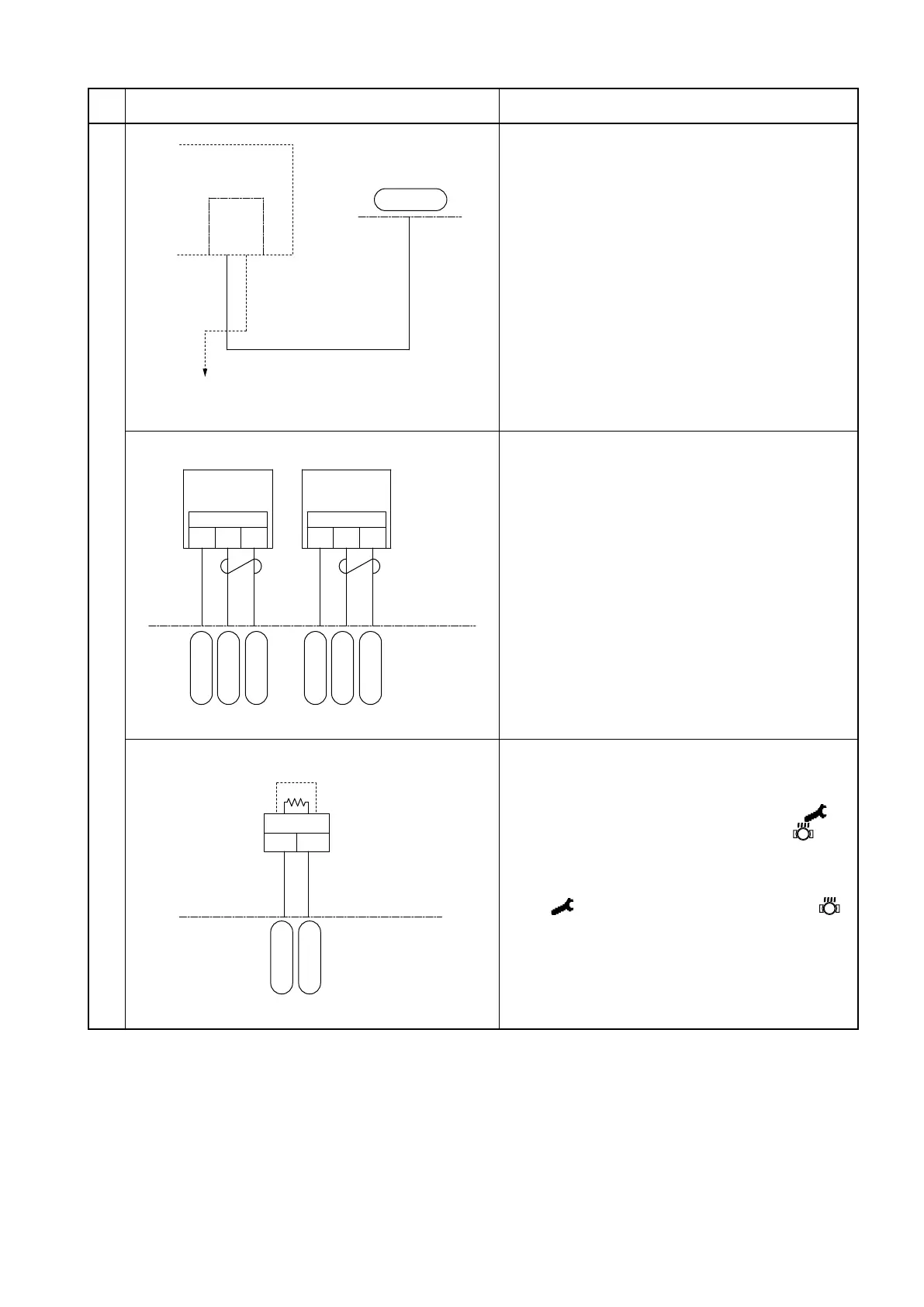
走行コントローラ
前進チャイムへ
リレーユニット
CN1D-33
F-20
F-18
(RF)
LB 180
WBr 97
7. RF relay (option)
(1) Activates the forward travel buzzer.
(2) When the F/R lever is placed in the F
position, the battery supplies voltage to the
CN1D-33 terminal. This activates the relay,
feeding power to the forward travel buzzer.
走行
コントローラ
CN2D-27
CN2D-3
CN2D-15
CN2D-29
CN2D-5
CN2D-16
2
3
1
(+)
(S) (-)
2
3
1
(+)
(S) (-)
RW 31
RB 32
RY 34
GW 28
GB 29
GY 33
回転センサA
回転センサB
8. Drive motor rotation sensor
(1) Detects the drive motor speed.
(2) When the drive motor runs, a pulsed
voltage is present between CN2D-3 and
CN2D-15 and between CN2D-5 and
CN2D-16.
走行コントローラ
2 1
WR 17
WG 16
走行モータサーモセンサ
CN2D-17
CN2D-6
9. Drive motor thermosensor
(1) Detects the drive motor temperature.
(2) When the sensor detects a temperature of
145°C [293°F] or above, the symbol
206 appears on the LCD panel, the
blinks, and the motor output is limited.
(3) When the sensor detects a temperature
of 156°C [312.9°F] or above, the symbol
205 appears on the LCD panel, the
blinks, and the motor is stopped.
Drive motor inverter unit
Drive motor
inverter unit
Drive motor inverter unit
Relay unit
to forward travel
buzzer
Rotation sensor A
Rotation sensor B
Drive motor thermosensor
 Loading...
