Circuit Diagram Description
Drive System
メータパネルへ
CN1D-5
CN1D-29
0 15
BR 9
パーキング
スイッチ
走行コントローラ
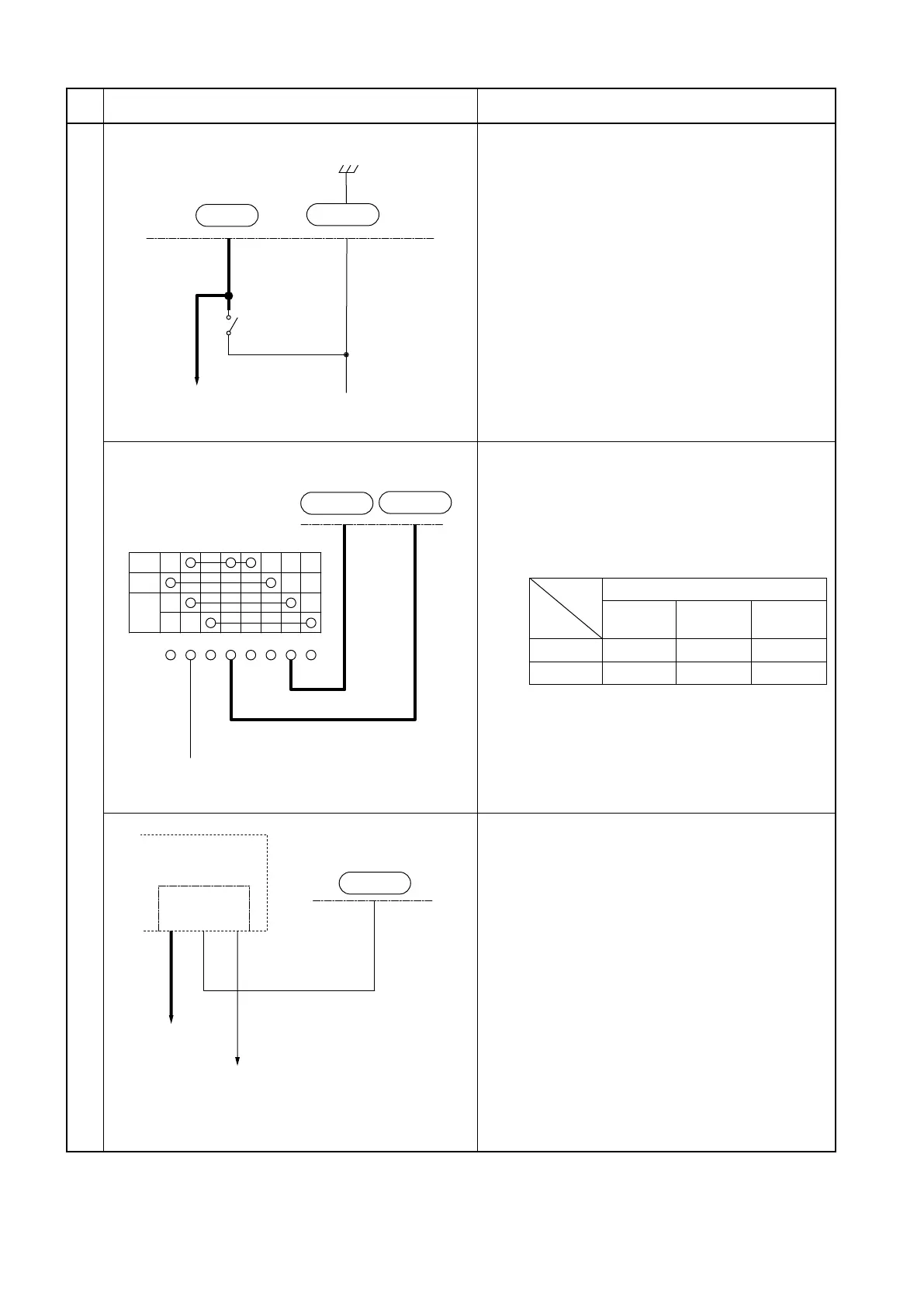
4. Parking brake switch
(1) When the parking brake lever is pulled, the
parking brake switch is turned on and the
“P” light on the LCD panel comes on. This
keeps the truck from moving.
(2) Voltage between CN1D-5 and CN1D-29
Parking brake lever pulled: 0V (switch
ON)
Parking brake lever released: 5V (switch
OFF)
走行コントローラ
CN1D-19
GND
CN1D-18
VF2
R
N
IG1 IG2 VF
N
F
ST VR Ra
WL 54
WBr 53
F/Rレバースイッチ
5. F/R lever switch
(1) This switch tells the inverter unit whether
the F/R lever is in the forward or reverse
travel position.
(2) Voltage between CN1D-18 and CN1D-19
Unit: V
Lever position
N
(Neutral)
F
(Forward)
R
(Reverse)
CN1D-18 4.6 0 4.6
CN1D-19 4.6 4.6 0
走行コントローラ
CN1D-34
F-21
F-2
F-22
(BB)
WB 98
LR 95
RW11
リレーユニット
バックアップランプ,
バックアップブザーへ
6. BB relay
(1) Activates the back-up buzzer and light.
(2) When the F/R lever is placed in the R
position, the battery supplies voltage to the
CN1D-34 terminal. This activates the BB
relay, feeding power to the back-up light
and buzzer.
Drive motor inverter unit
Parking
switch
to LCD panel
F/R lever switch
Drive motor inverter unit
Drive motor inverter unit
Relay unit
to back-up light and
buzzer
 Loading...
