- 10 -
1. CONTROL CIRCUITS
Circuit Diagram Description
Others
RL100
CN1D-24
CN1P-24
CN1P-22
CN1E-34
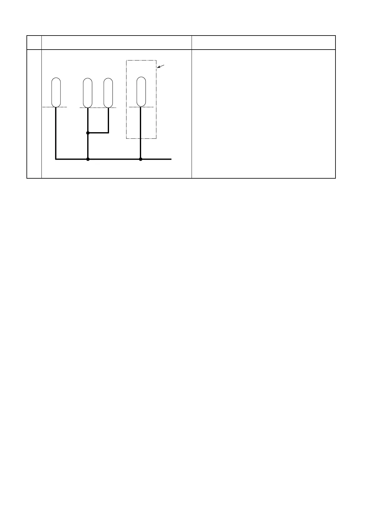
3. CN1D-24, CN1P-24, CN1P-22, and CN1E-34
terminals
When the battery is connected, the battery
voltage is present at these terminals.
These terminals are used to detect the battery
voltage.
Drive motor
inverter unit
Pump motor
inverter unit
PS motor
controller
Excluding
trucks with
an Orbitrol
steering
system.
11i
r'
/〆一、
r、
[]
冒4ど
冒i
..L
L
」
 Loading...
