14
www.tcsmeters.com
Total Control Systems
TCS 3000 Installation
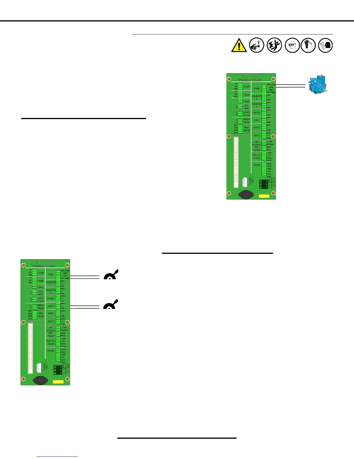
Installaon Procedure — Pump & Throle
RED
BLACK
Installaon Procedure:
1. Locate the Pump Control (PMP. CRL) posion on the terminal
board.
2. Screw the cable gland into the back of the TCS 3000 register and
ghten into the housing.
3. Run the Pump Control to the onboard computer or programma-
ble logic controller (PLC) wiring through the cable gland. Wire the
air eliminator oat into the correct locaon on the terminal
board. Leave a small amount of slack on the wiring.
4. Compress the cable gland on the TCS3000 register unl it is snug
on the air eliminator oat wiring.
The Pump Control is ulized as a posive output signal for the enre delivery pro-
cess. Providing security pump authorizaon and more accurate deliveries. Some-
mes required to be used with onboard computer systems or programmable logic
controllers (PLC).
BLACK
RED
RED
BLACK
THROTTLE 1
THROTTLE 2
Installaon Procedure:
1. THROTTLE 1: Locate the Pump Starter (PMP START) port on ter-
minal for Throle 1 posive output signal based on Flow Rate.
WARNING: Throle 1 product selecon will override the Addive
Injecon parameter if selected.
2. THROTTLE 2: Locate the Auxillary 1 (AUX 1) port on terminal for
Throle 2 posive output signal based on Flow Rate.
3. For both Throle outputs, wire signal wire to (+) and ground to
(GND).
PUMP CONTROL
 Loading...