7
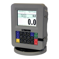
TCS 3000 Installation
www.tcsmeters.com Total Control Systems
Installaon Procedure — TCS 700 Series Meter
Before beginning the installaon of the TCS 3000 register, unpack the enre contents of the packaging in a safe loca-
on where you will not misplace any of the parts. Lay out the parts as they would be installed on the truck. This will
ensure that you have all the correct parts for the installaon. Verifying all the necessary parts were included in the
shipment in advance will reduce the truck downme and avoid any wasted truck preparaon work.
Item Qty TCS 300870
Metric
TCS 300970
NPT
Phillips Pan 6 TCS300137 TCS300137
Spring Washer 6 TCS300138 TCS300138
Terminal Cover 1 TCS300164 TCS300164
7.5 AMP Fuse 1 TCS300192 TCS300192
Fuse Holder 1 TCS300193 TCS300193
Cable Gland 4 TCS300244 TCS300133
O-Ring, Cable Gland 4 TCS300245 TCS300245
USB Fem/Mini Male Cable 1 TCS300705 TCS300705
Resistor 1K OHM 2 TCS300753 TCS300753
1/4—28X1 Zinc Bolt 2 TCS68013 TCS68013
1/4-28X1 Drilled Bolt 2 TCS68013D TCS68013D
3/64 X 1 Coer Pin 1 TCS790091 TCS790091
700 Meter Drive Coupling 1 TCS790092 TCS790092
Installaon Procedure:
1. Remove and put aside the four mounng bolts and any mounng adaptor. Remove the exisng mechanical regis-
ter or electronic register, if applicable. Use a box or container to set old equipment and parts in.
2. Remove adjuster dust cover plate from the front of the meter. Remove exisng adjuster. Set adjuster dust cover
aside in a box or container where it will not be misplaced. Screw the screws back into meter unit. Noce the type
of vercal drive sha in the meter.
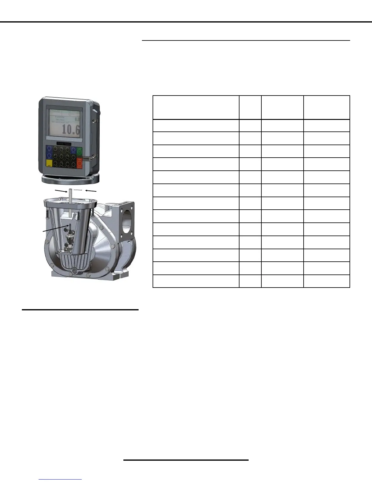
3. Using the sha specic to your installaon, slide the Drive Coupling on the Pulser and align the holes. Once the
holes are aligned insert the Coer Pin and bend the pin ends back around the Drive Coupling.
4. Slide the Drive Coupling onto the Meter Drive Sha.
5. Rotate the TCS 3000 register unl the display is facing in the desired direcon and check to see that the meter
holes align with the holes at the base of the TCS 3000 register.
6. Secure the bolts.
700 Drive Coupling
Coer Pin
700 Drive Sha