32
www.tcsmeters.com
Total Control Systems
TCS 3000 Installation
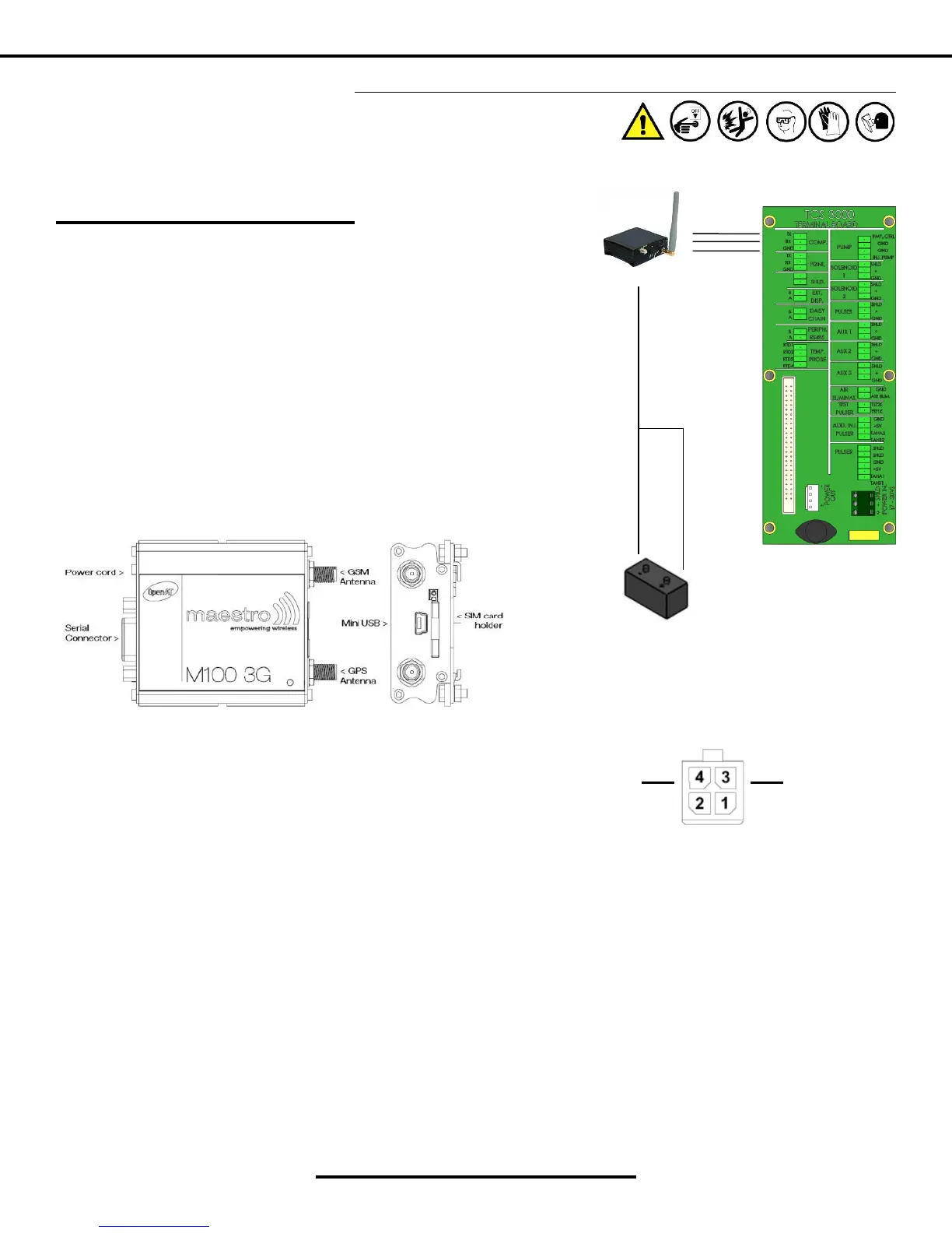
WHITE (Ground)
GREEN (Posive)
BROWN
BLUE
BLACK
Installaon Procedure — Maestro Cellular Modem
EXTERNAL POWER SOURCE
Installaon Procedure
1. Wire the 15DB Pin Communicaon Cable to the Computer (COMP.) port of
the TCS 3000 register terminal board.
2. Cellular modems come with a Power Cable & Plug. The Green wire must
be wired to the External Power Source (accessory switch) together. The
White wire must be wired to Baery ground.
3. Antenna must be connected to cellular modem for there to be any acvity.
4. Cellular modems will be required to have proper programming prior to
use.
Status Indicator
The LED will indicate dierent status of the modem:
• OFF: modem is switched o
• ON: modem has no network and GPS doesn’t have a x
• ON, and OF pulse every 10 seconds: modem has no network and GPS has a x
• Flashing slowly: modem is registered on the network and GPS doesn’t have a x
• Flashing rapidly: modem is registered on the network and GPS has a x
WHITE ( - ) GREEN ( + )
4-Pin Power Connector
 Loading...