30
P42
Maximum torque CCW
P43
Maximum torque CW
D30
P98
1P23
V controller
brake
C47
-
+
Vbus_rif
Vbus
regulator
C34=1 Mns off
C34=1
C47
P41
Maximum
motor
torque
Maximum torque
set by current limit
-
-
-
)
2
Φnom
Φ
-
)
Φnom
Φ
sysMaxTorque
sysMaxPositiveTorque
sysMaxNegativeTorque
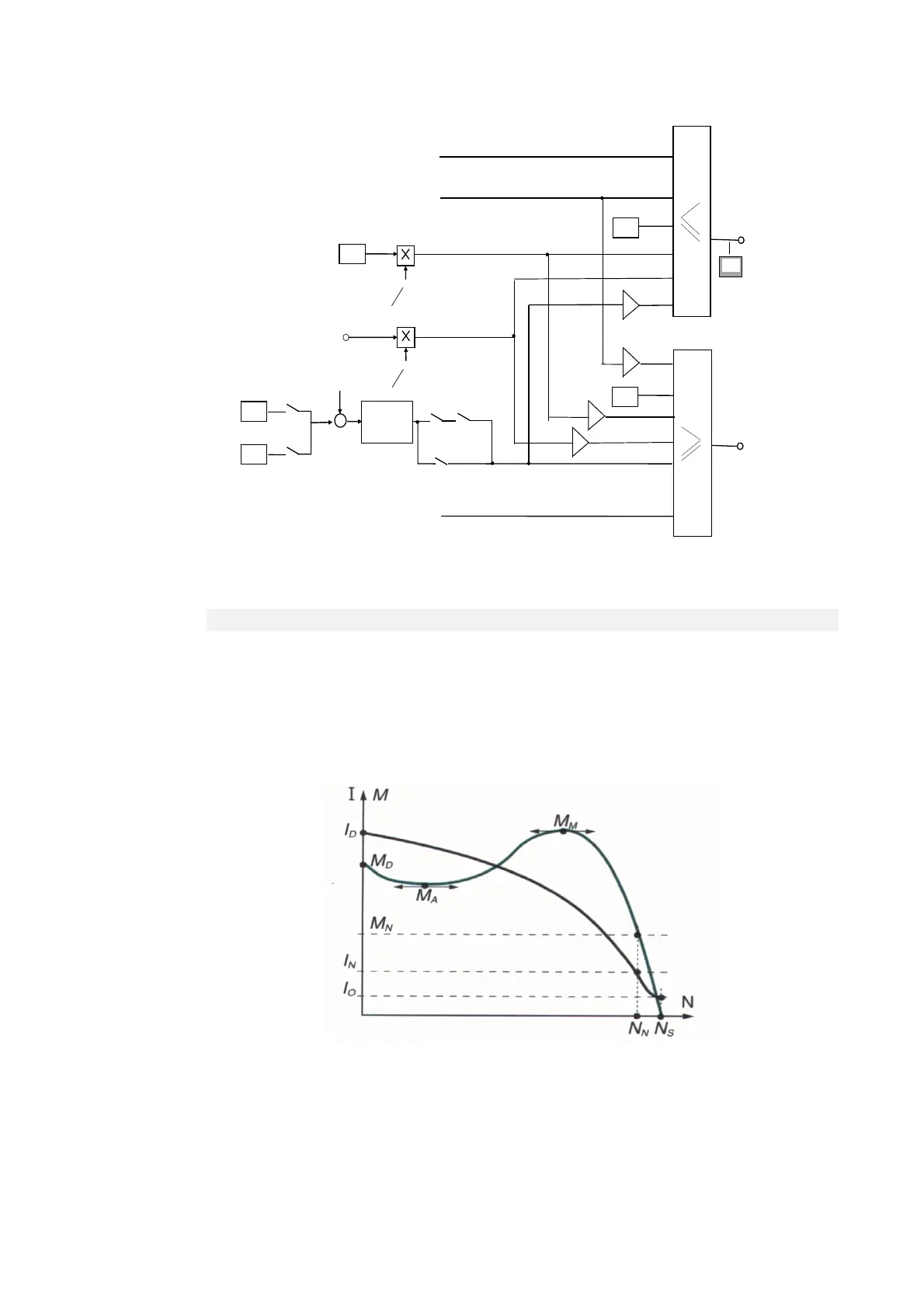
2.2.3.2 MAXIMUM MOTOR TORQUE LIMIT
The induction motor has a maximum torque that depends on its construction characteristics.
The graph below illustrates the progress of a torque curve according to speed with the motor
powered by a constant frequency (Ns). The same graph can also be referred to when an inverter is
used, reading it as torque delivered according to slip, i.e. the difference between the rotation speed of
the electrical values and the rotor (Ns – N in the graph).
The graph illustrates how the delivered torque increases according to slip up to a certain point
represented by the maximum motor torque. If the maximum torque is exceeded, control is lost in that
the torque decreases even when the current is increased.
3-phase induction motor torque (M) and current (I)
curve accordin
to number of revolutions
N
.
Id = starting current
In = rated current
Io = no-load current
Md = starting torque
Ma = acceleration torque
Mm = max. torque
Mn = rated torque
Nn = rated speed
Ns = synchronism speed