84
5.8
Multi Power Supply Connection (Daisy-Chain) to RS232,
RS485, USB or LAN
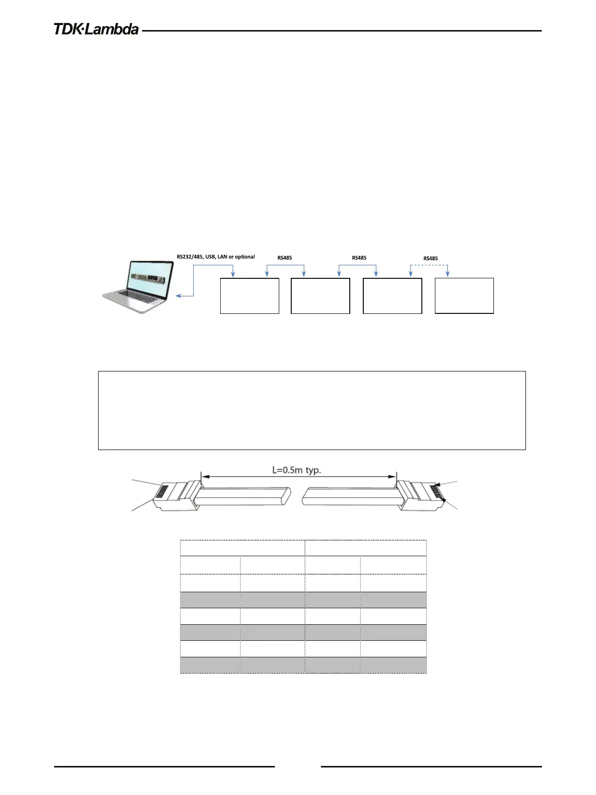
A Daisy-chain configuration of up to 32 units can be connected to RS232, RS485, USB, LAN or
optional communication (i.e. IEEE). The first unit connects to the controller or PC via RS232,
RS485, USB, LAN or optional communication, while the RS485 bus connects the other units. The
user must set all Power Supplies in the chain to a unique address.
1. First unit connection: Select a communication Interface. Refer to section 5.2.2.
2. Other units’ connection: The other units on the bus are connected via RS485 interface. Refer
to Figure 5–21 for typical connections.
3. Using the Linking cable supplied with each unit (Refer to Figure 5–21), connect each unit’s
OUT connector to the next unit’s IN connector.
Figure 5–21: Multi Power Supplies RS232/485, USB or LAN Connection
NOTE:
If ten or more Power Supplies are connected in a Daisy-chain configuration, it is recommended to
connect 120Ω resistive termination at the last unit’s RS-485 OUT connector:
120Ω, 0.5W between TXD+ to TXD-.
120Ω, 0.5W between RXD+ to RXD-.
Table 5-2: Serial Link Cable with RJ-45 Shielded Connectors (P/N: GEN/RJ45)
#0
#1
#2
IN OUT
POWER SUPPLY
#31