17
NOTE
* LAN Connector LEDs (Green & Amber) and Red Status Indicators might lit in Power Switch OFF
state.
WARNING
Refer to the Safety & Installation Manual for any connect/disconnect of any connector on the rear
panel.
2.5
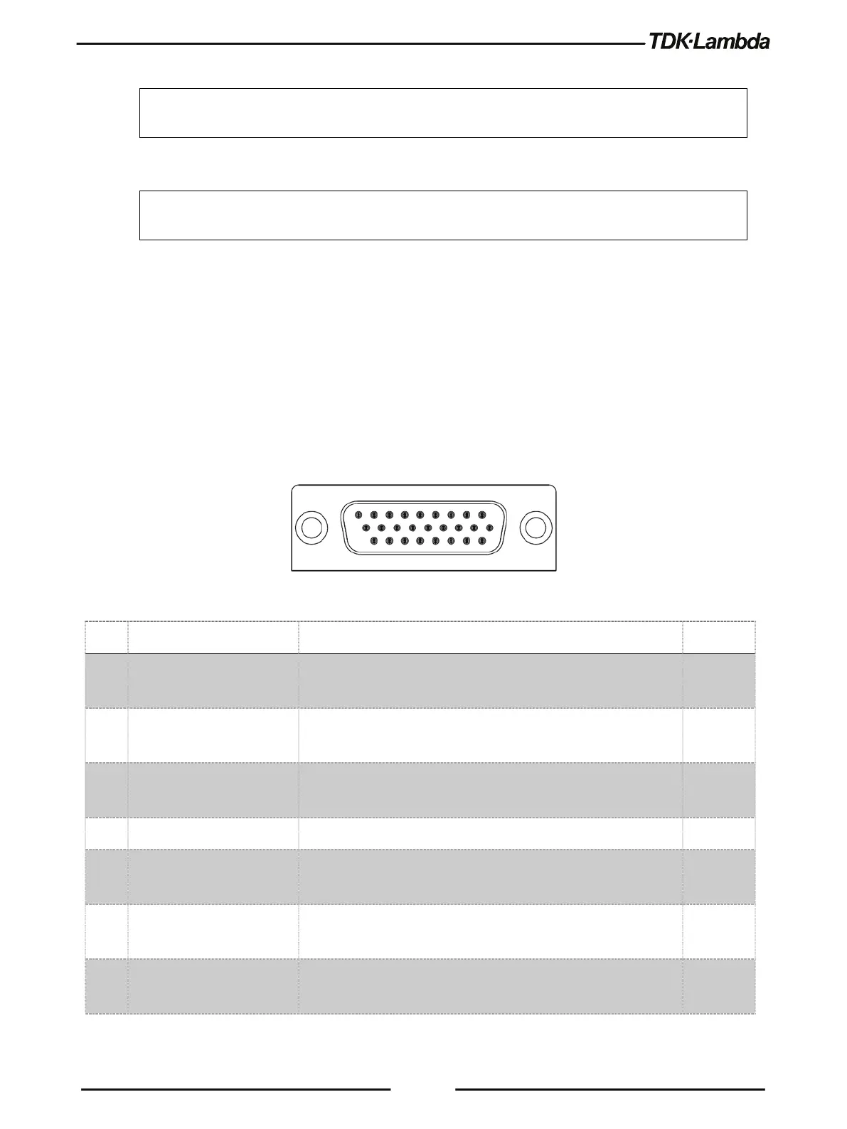
J1 Connector Terminal and Function
Control and monitoring signals are SELV.
Connector Technical Information:
Connector type: 618026325223, WURTH
DB26HD Receptacle type: 10090769-P264ALF, FCI
Wire: AWG 24-28
Figure 2–4: J1 Connector Terminals and Functions
1 Daisy In / SO Input for Series Operation / Input for Shut Off control of the
2 Daisy Out / PS_OK #2 Output for Series Operation / Output #2 for indication of power
supply status. High level is OK.
3 PS_OK #1 Output #1 for indication of power supply status. Open Collector
Output for Constant-Voltage / Constant-Current mode indication.
5 LOC/REM MON Output for indicating if the unit is in Local (digital) or Remote
(analog) programming mode.
6 LOC/REM SELECT Input for selecting between Local (digital) or Remote (analog)
programming of the output Voltage and Current.
7 IPGM Input for Remote (analog) voltage/resistance programming of