10
CHAPTER 2: FRONT/REAR PANEL CONTROL & CONNECTORS
2.1
Introduction
The Power Supply series has a full set of controls, indicators and connectors that allow
the user to setup and operate the unit. Before starting to operate the unit, please read the following
sections for an explanation of the functions, controls and connector terminals.
•
Section 2.2: Front Panel Controls
•
Section 2.3: Front Panel Display and Indicators.
•
Section 2.4: Rear Panel Connections and Controls
•
Section 2.5: J1 Connector Terminal and Function
2.2
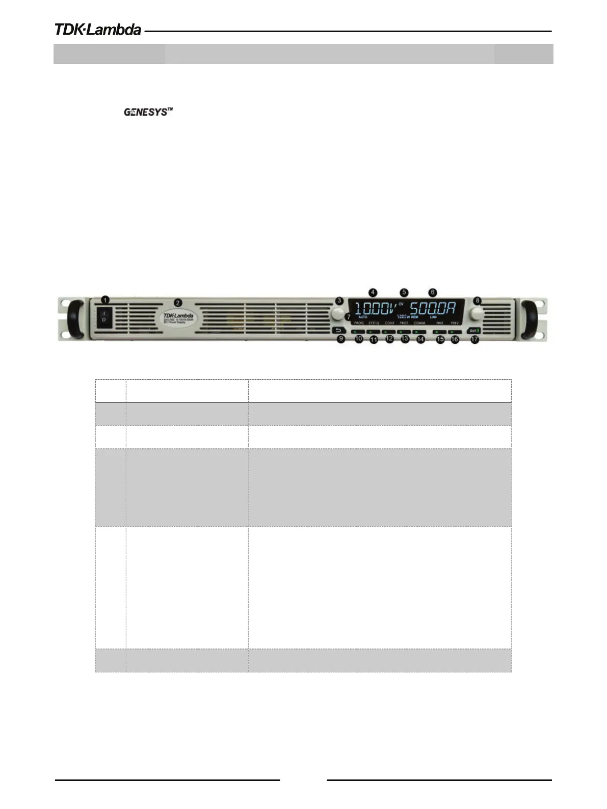
Front Panel Controls
Refer to Figure 2–1 and Table 2-1 for description of the Front Panel controls.
Figure 2–1: Front Panel Controls
Model, Voltage & Current Identifier.
3 Voltage Encoder and
Button
Encoder: A high-resolution detent rotary Encoder adjusting
the output voltage and navigating menu.
Button: An auxiliary function to accept the voltage-setting
4 Voltage Display 4-digit 16-segment Voltage display.
Normally displays the output voltage.
In Preview mode, the display indicates the program setting of
the output voltage.
In Menu navigation, the display indicates the selected
CV/CC/CP Operation mode indicator.