What the Controls Do-222 DSO Operators
Table
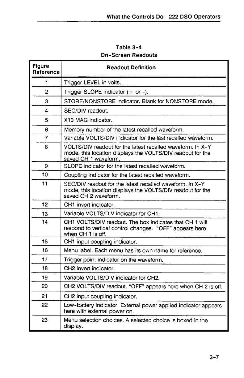
3-4
On-Screen Readouts
Figure
Reference
1
3
1
STOREINONSTORE indicator. Blank for NONSTORE mode.
Readout Definition
Trigger LEVEL in volts.
2
4
1
SECIDIV readout.
Trigger SLOPE indicator
(+
or
-).
5
1
XI0 MAG indicator.
6
1
Memorv number of the latest recalled waveform.
7
1
Variable VOLTSIDIV indicator for the last recalled waveform.
8
9
12
1
CHI invert indicator
VOLTSIDIV readout for the latest recalled waveform. In X-Y
mode, this location displays the VOLTSIDIV readout for the
saved CH 1 waveform.
SLOPE indicator for the latest recalled waveform.
10
11
Coupling indicator for the latest recalled waveform.
SECIDIV readout for the latest recalled waveform. In X-Y
mode, this location displays the VOLTSIDIV readout for the
saved CH 2 waveform.
I
15
1
CHI in~ut cou~lina indicator.
13
14
16
1
Menu label. Each menu has its own name for reference.
Variable VOLTSIDIV indicator for CHI.
CHI VOLTSIDIV readout. The box indicates that CH 1 will
respond to vertical control changes.
"OFF" appears here
when CH 1 is off.
17
18
Trigger point indicator on the waveform.
CH2 invert indicator.
19
20
2 1
22
23
Variable
VOLTSIDIV indicator for CH2.
CH2 VOLTSIDIV readout. "OFF" appears here when CH 2 is off.
CH2 input coupling indicator.
Low-battery indicator. External power applied indicator appears
here with external power on.
Menu selection choices.
A
selected choice is boxed in the
dis~lav.