C ircuit Description—434
backplate voltage is gradually returned, the target is charged
to the rest potential and the target is in the ready-to-write
state.
For a comprehensive study of storage tube operating
principles, a T ektronix C ircuit Concepts paperback book
entitled "Storage Cathode-Ray Tubes and C ircuits" is
available through your local Tektronix, Inc., Field Office or
representative. Tektronix Stock No. 062-0861-00.
Flood Guns and Collim ation Electrodes
Tw o low-energy electron guns, or flood guns, are used in
the 434. The cathodes are returned to —75 volts through
INTEGRATE switch S94 and R94. R 1298 and VR 1298 set
the level of the flood-gun control grid at approximately
+ 140 volts.
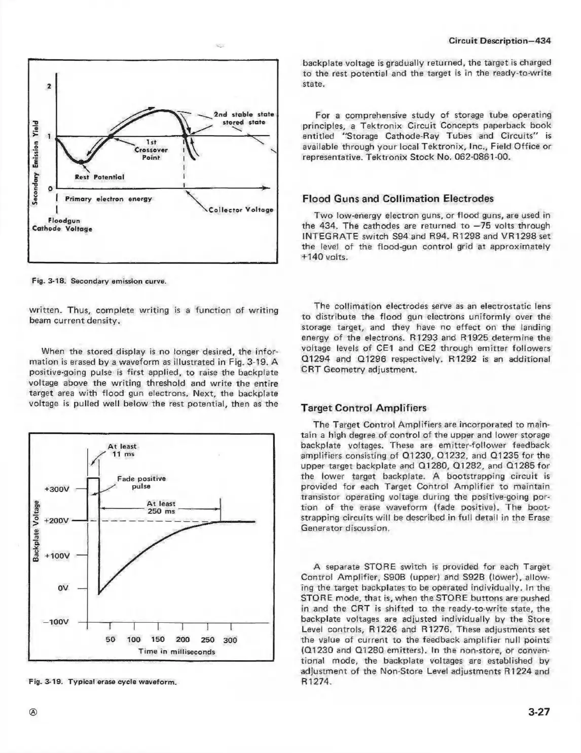
Fig. 3-18. Secondary em ission curve.
w ritten. Thus, complete w riting is a function of w riting
beam current density.
When the stored display is no longer desired, the in for
mation is erased by a waveform as illustrated in Fig. 3-19. A
positive-going pulse is first applied, to raise the backplate
voltage above the w riting threshold and w rite the entire
target area with flood gun electrons. Next, the backplate
voltage is pulled well below the rest potential, then as the
Fig. 3-19. T y pical erase cycle w aveform .
The collim ation electrodes serve as an electrostatic lens
to distribute the flood gun electrons uniform ly over the
storage target, and they have no effect on the landing
energy of the electrons. R1293 and R1925 determine the
voltage levels of CE1 and CE2 through emitter followers
Q1294 and Q1296 respectively. R1292 is an additional
CRT Geometry adjustment.
Target Control Am plifiers
The Target Control Am plifiers are incorporated to main
tain a high degree of control of the upper and lower storage
backplate voltages. These are em itter-follower feedback
amplifiers consisting of Q1230, Q1232, and Q1235 for the
upper target backplate and Q1280, Q1282, and Q1285 for
the lower target backplate. A bootstrapping circuit is
provided for each Target Control A m plifier to maintain
transistor operating voltage during the positive-going por
tion of the erase waveform (fade positive). The boot
strapping circuits w ill be described in fu ll detail in the Erase
Generator discussion.
A separate STORE switch is provided for each Target
Control A m plifier, S90B (upper) and S92B (lower), allow
ing the target backplates to be operated individually. In the
STORE mode, that is, when the STORE buttons are pushed
in and the CRT is shifted to the ready-to-write state, the
backplate voltages are adjusted individually by the Store
Level controls, R1226 and R1276. These adjustments set
the value of current to the feedback am plifier null points
(Q1230 and Q1280 emitters), in the non-store, or conven
tional mode, the backplate voltages are established by
adjustment of the Non-Store Level adjustments R1224 and
R 1274.
3-27