Adjustment Procedures
1. Install the tes
t hookup and preset the instrument controls:
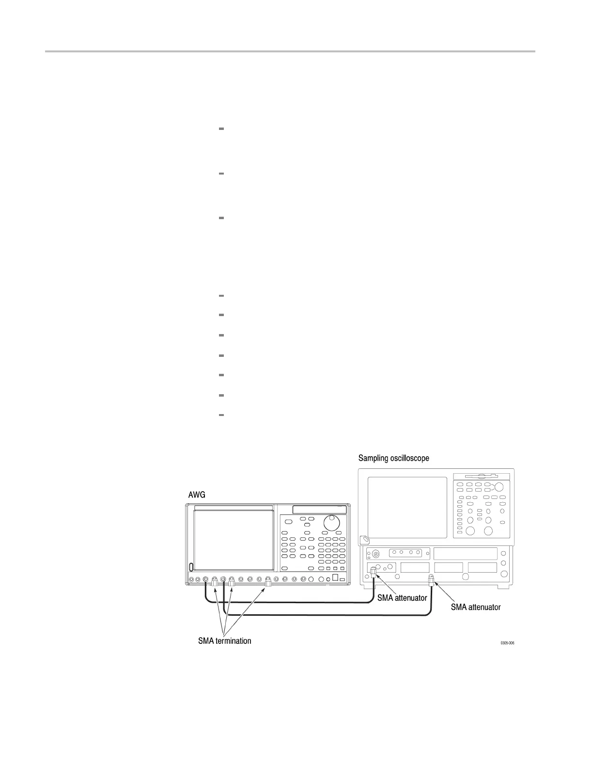
a. Hook up the sampling oscilloscope:
Attach the SMA terminations to the Channel 1 Analog (–) Output,
Channel 2 Analog (–) Output, and Marker 1 (–) Output on the front
panel of the arbitrary waveform generator.
Connect an SMA cable from the Channel 1 Analog (+) Output on the
front panel of the arbitrary waveform generator to the CH 1 Input of
the sampling oscilloscope using the 12 dB SMA attenuator.
Connect an SMA cable from the Channel 1 Marker 1 (+) Output on
the front panel of the arbitrary waveform generator to the TRIGGER
DIRECT INPUT of the sampling oscilloscope using the 12 dB SMA
attenua
tor. (See Figure 3-4.)
b. Set the sampling oscilloscope as follows:
Vertical External Attenuation: 12 dB
Vertical Scale: 200 mV/div
Horizontal Scale: 50 ps/div
Horizontal Timebase Mode: Lock to INT. 10 MHz
Trig
ger: External Direct Input, Level 50%
Acquisition: Average 64, Stop After Condition: Average Complete
Measurement: R1 to C1 Delay (R1/C1 Reference Level: Absolute
0.0 V)
Figure 3-4: Inter-channel skew calibration initial hookup
3–8 AWG7000B and AWG7000C Series Service Manual

 Loading...


