Removal and Installation Procedures
Power Board
You need a scr ew
driver with a T-15 Torx tip (items 1 and 2).
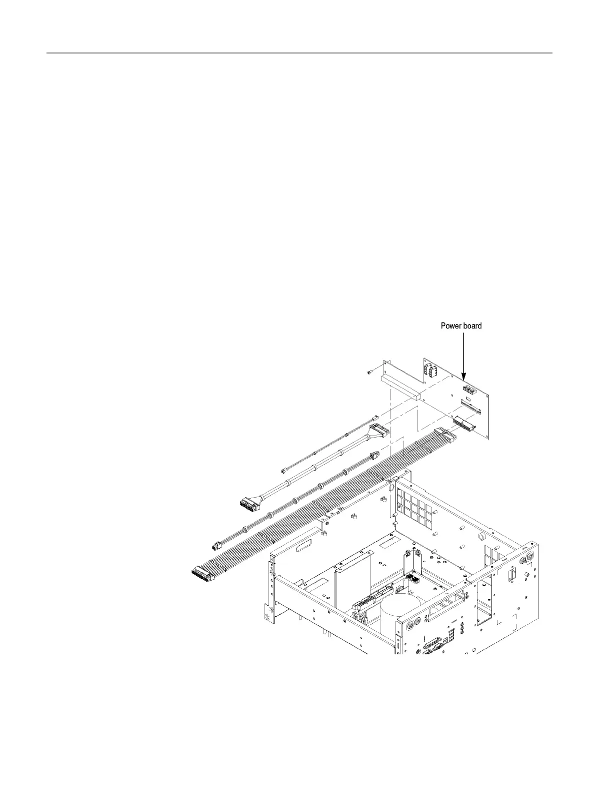
Removal. To remove the Power board, follow these steps: (See Figure 4-18 on
page 4-38.)
1. Remove the handle unit, snaps, cosmetic covers, front-trim unit, EMI covers,
MIO board enforcement bracket, hard disk assembly, drive- bay module,
power supply, Multi-Input/Output board, and Processor board.
2. Orient the instrument so that the bottom is on the work surface.
3. Disconnect the c ables from J102, J103, J120, J300, J302, J304, J600, and
J611 on the Power board.
4. Remove the 10 screws securing the Power board to the chassis.
5. Lift the board away from the chassis.
Installation. To install, reverse this procedure.
Figure 4-18: Power board removal (AWG7000B Series)
4–38 AWG7000B and AWG7000C Series Service Manual

 Loading...


