Removal and Installation Procedures
AWG12G1CHBoard
(AWG7000B Series Only)
Youneedascrew
driver with a T-15 Torx tip and pliers (items 1, 2, and 8).
Removal. To remove the AWG12G 1 channel board, follow these steps: (See
Figure 4-19 on page 4-40.)
1. Remove the handle unit, snaps, cosmetic covers, front-trim unit, EMI covers,
CLK12G module, and relay unit (for Optio n 02).
2. Orient the instrument so that the top is on the work surface.
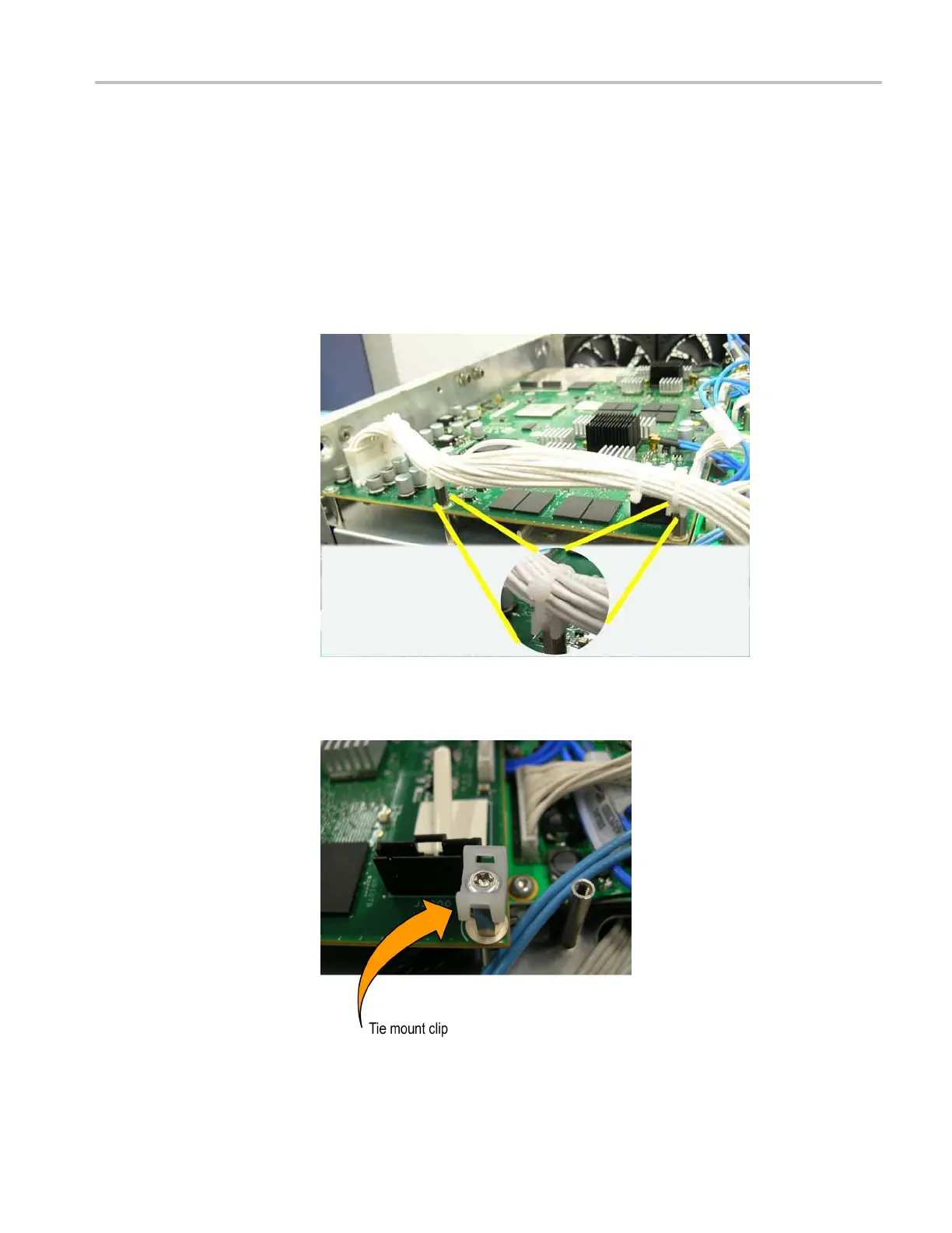
3. Use a wire cutter to remove the two cable ties.
Figure 4 -23: Cable ties
4. Remove the two screws, and then remove the tie mount clips.
Figure 4-24: Tie mount clip
AWG7000B and AWG7000C Series Service Manual 4–45

 Loading...


