Removal and Installation Procedures
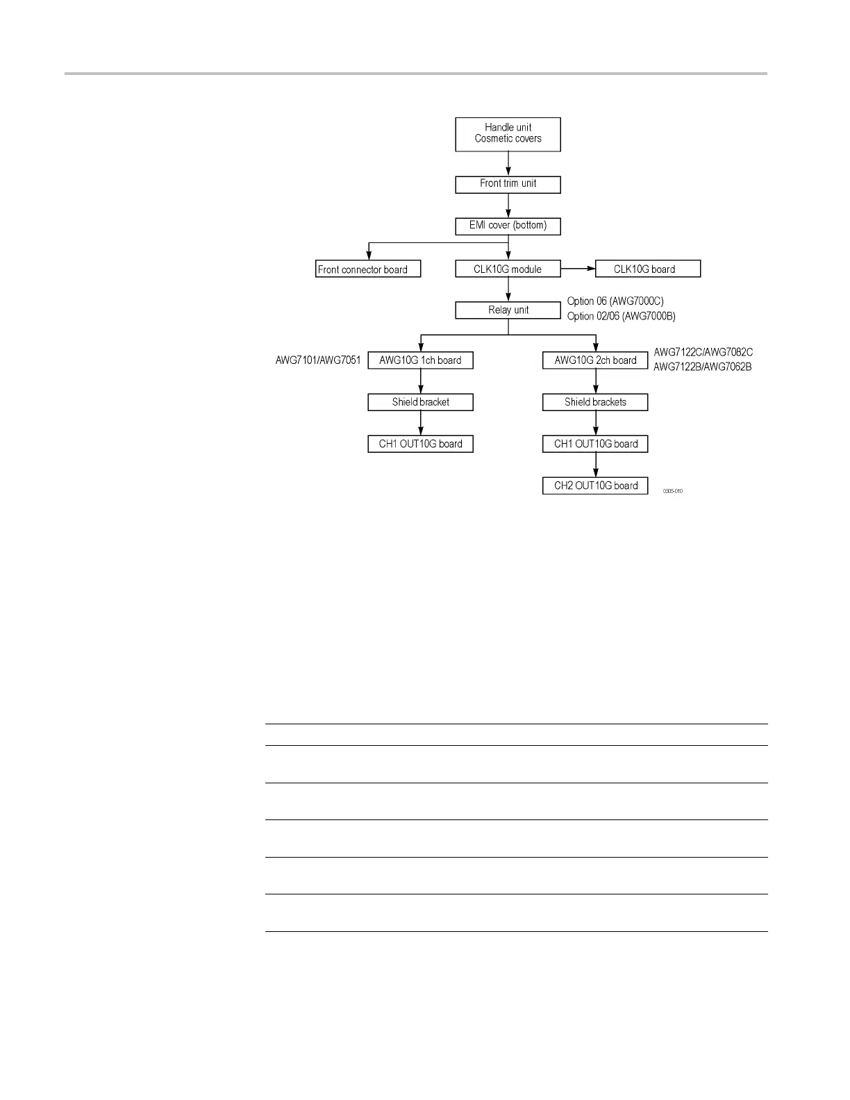
Figure 4-2: Disassembly procedures for internal modules (bottom)
Requir
ed Equipment
Most modules in the instrument can be removed with a screwdriver handle
mounted with a size T-15, Torx screwdriver tip. All equipment required to remove
and re
install the modules is listed in the following table.
Table 4-3: Tools required for module removal and reinstall
Item # Name Description General Tool #
1.
Screwdriver handle
Accepts Torx-driver bits 620-440
2. T-15 Torx tip
Torx-driver bit for T-15 size
screw heads
640-247
3. T-10 Torx tip
Torx-driver bit for T-10 size
screw heads
4. T-20 Torx tip
Torx-driver bit for T-20 size
screw heads
5.
#1 Phillips screwdriver Screwdriver for removing
#1 size Phillips screws
Standard tool
6.
#2 Phillips screwdriver Screwdriver for removing
#2 size Phillips screws
Standard tool
4–8 AWG7000B and AWG7000C Series Service Manual

 Loading...


