Removal and Installation Procedures
Relay Unit (for Option 02)
(AWG7000B Series Only)
Youneedascrew
driver with a T-15 Torx tip and a 5/16 inch torque wrench (items
1, 2, and 9).
Removal. To remove the relay unit, follow these steps: (See Figure 4-19 on
page 4-40.)
1. Remove the handle unit, snaps, cosmetic covers, front-trim unit, and EMI
covers.
2. Orient the instrument so that the top is on the work surface.
3. Use a 5 /16 inch torque wrench to remove the six SMA cables (or 12 SMA
cables for 2 channel models) from the relay units.
4. Disconnect the cable (or two cables for 2 channel models) from the relay units.
5. Remove the 10 screws securing the rela y unit to the chassis.
6. Lift the relay unit away from the chassis.
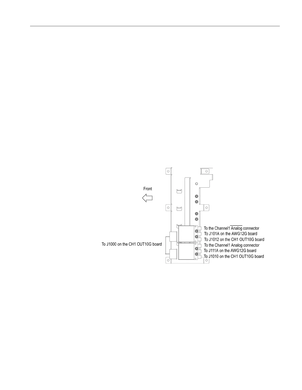
Installation. To install, reverse this procedure. (See Figure 4-21.)
Figure 4-21: Relay unit cable connection for option 02
Relay Unit ( fo r Option 06)
You need a screwdriver w ith a T-15 Torx tip and a 5/16 inch torque wrench (items
1, 2, and 9).
Removal. To remove the relay unit, follow these steps: (See Figure 4-19 on
page 4-40.)
1. Remove the handle unit, snaps, cosmetic covers, front-trim unit, EMI covers.
2. Orient the instrument so that the top is on the work surface.
AWG7000B and AWG7000C Series Service Manual 4–43

 Loading...


