& %#%
"#% !#%!
2Ć6
3. Select the appropriate input channel, channel 1 or channel 2, by pressĆ
ing the or frontĆpanel button.
4. With the probe attached between an input channel and the probe comĆ
pensation output of the oscilloscope, press the button on the
front panel.
5. Set the vertical scale to 1 V using the control.
6. Center the waveform vertically using the vertical control.
7. Set the horizontal scale to 200 ms using the control.
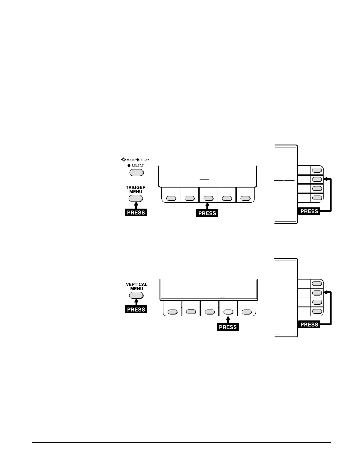
8. Set the trigger coupling to !$ % (use the following guide).
MAIN TRIGGER MENU
MODE SRC CPLG SLOPE HOLDOFF
Auto Ch1 Noise
Rise Off
DC
Noise Reject
HF Reject
MORE
1of2
9. Set the vertical bandwidth to & (use the following guide).
CHANNEL 1 MENU
CPLG VAR INV BW
AC Off Off Full
20 MHz
Full
10. Check that the displayed waveform is a square wave with flat tops and
bottoms. See Figure 2Ć6 for illustrations indicating proper and improper
probe compensation.

 Loading...
