Getting Started
1-28
TDS3000B Serie s User Manual
5. Waveform record icon shows the trigger locat ion relative to the
waveform record. The lin e c olor corresponds to the selected
waveform color.
6. Trigger status readout show trigger status.
7. Trigger level ic on shows the tri gger level on the waveform. The
icon c olor corresponds to the trigger source channel color.
8. Cursor and measurement readouts show results and me ssages.
9. Trigger readouts show the trigger sources, slopes, and leve ls, and
position.
10. Readout shows the delay setting or the trigger location within the
record.
11. Horizontal readout shows the main or zoom time/division.
12. Auxiliary waveform readouts show the vertical a nd horiz onta l
scale factors of the math or reference waveforms.
13. Channel readouts show the cha nnel scal e factor, coupling, input
resistance, bandwidth limit, and invert status.
14 15
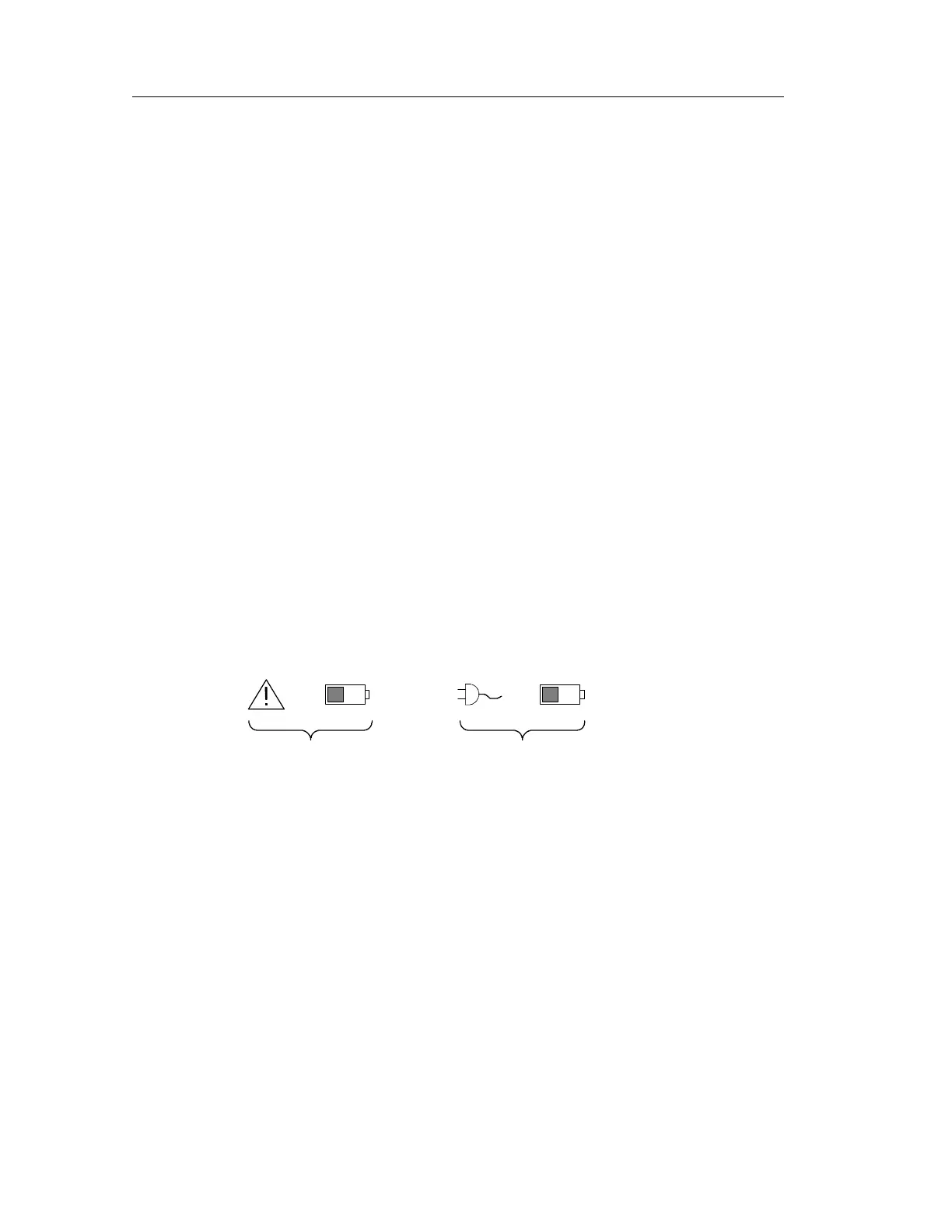
14. Triangle icon with the battery icon indicates a battery is installed
and battery power is in use. The battery icon shows the
approximate charge level of t he battery. See page 1--13 for
important safety information.
15. Power-plug icon with the battery icon indicates a battery is
installed but line power is in use. The battery may be charging.
The battery icon shows the approximate charge level.
 Loading...