93
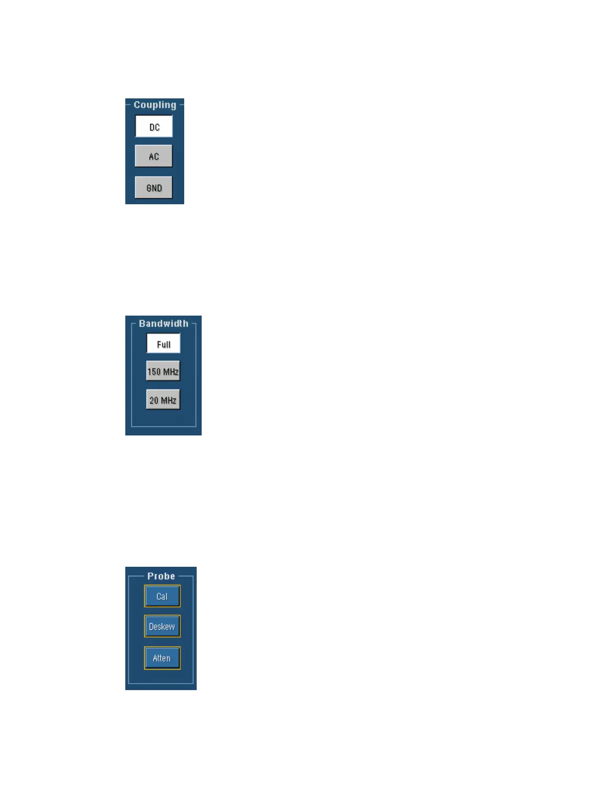
Coupling Setup
To Use
Use the Coupling controls to couple the signal from the attached probe to the
instrument.
Behavior
Select DC to display the waveform with the DC and the AC components.
Select AC to display the waveform with the DC component removed.
Select GND to display a zero-volt waveform. Use this selection to establish the ground reference
point on the display.
Note
The 50 Ω channel input termination becomes an open circuit when you select GND coupling.
Bandwidth
To Use
Use the Bandwidth controls to filter unwanted high frequency noise from
the waveform and to decrease the noise bandwidth. Specify the range of
frequencies that you want to acquire by clicking the appropriate button in
the control window.
Behavior
The bandwidth refers to the range of frequencies that the instrument can
acquire and display accurately with less than 3dB attenuation. Each input
channel has its own bandwidth selection.
To acquire all frequencies on the selected channel, click Full. To limit frequencies above
150 MHz, click 150 MHz; to limit frequencies above 20 MHz, click 20 MHz.
To take accurate measurements, the input frequency should be much less than the rated bandwidth
of the instrument. A good rule to follow is to ensure the bandwidth of the instrument system is
three to five times the bandwidth of the signal that you want to measure.
Probe Controls
The Probe controls provide access to the Probe Calibration, Deskew, and
Attenuation control windows.
Use the Probe Calibration control window (Cal) to check the status of the
attached probe and to compensate the entire signal path from the probe tip
to the digitized signal.
Use the Deskew control window to compensate the vertical channels for
propagation delays of different length probes.
Use the Attenuation control window (Atten) to change the default
attenuation or gain for the selected probe channel.
 Loading...


