Table 18: AC CMRR test equipment settings
Probe Generator output
Model Range Voltage (p-p) Frequency
THDP0100 600 V 297 V 100 kHz
THDP0200 150 V 297 V 100 kHz
TMDP0200 75 V 297 V 100 kHz
4. Set the oscilloscope horizontal to 10
μs/div.
5. Set the probe bandwidth to full and the attenuation to the lower range of the probe.
6. Enable the generator output. Adjust the oscilloscope vertical to display the signal.
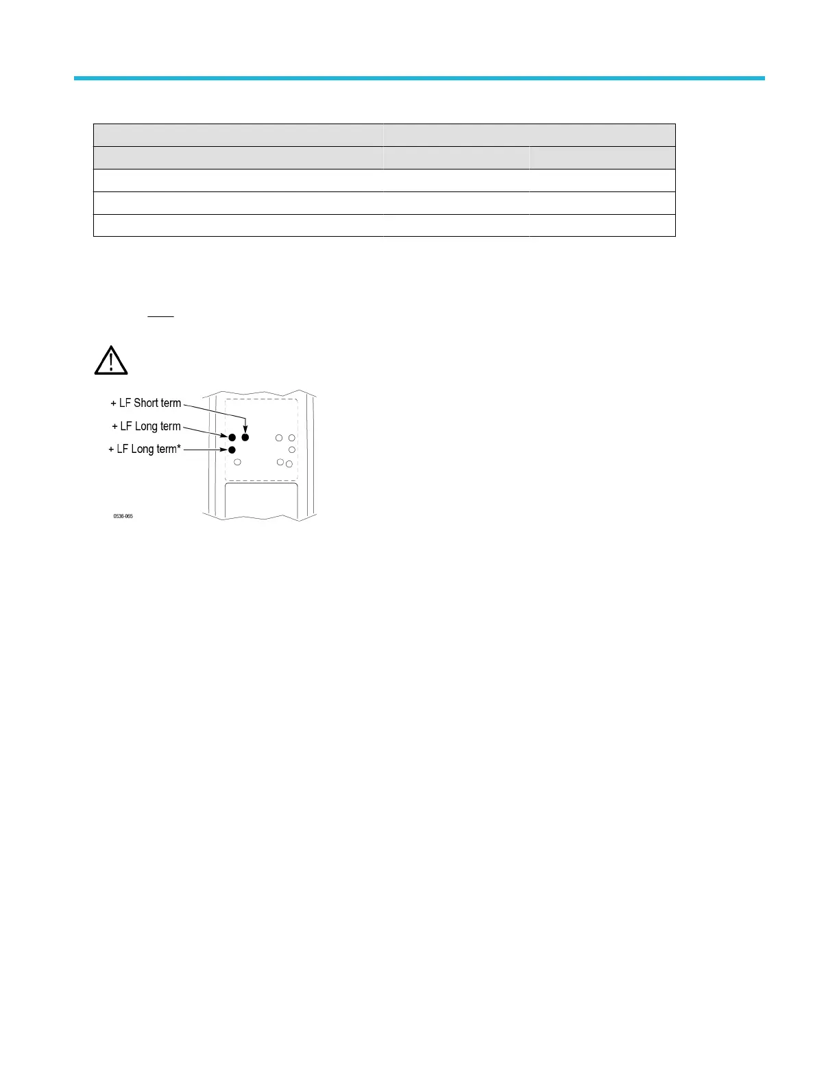
7. Make only
slight adjustments to only the +LF pots to optimize the CMRR (minimize the signal amplitude). Adjust the pots in the
following order: short-term +LF
, long-term +LF, long-term +LF*. (The long-term +LF* adjustment is not used in the TMDP0200 probe.)
WARNING: Use only an insulated tool to make the adjustment. Failure to do so presents a potential shock hazard.
This completes the adjustment procedures.
Adjustments
60

 Loading...


