Video and General Performance Verification Procedures
Figure 4: Trigger polarity positive
7. Change the oscilloscope trigger polarity to Neg.
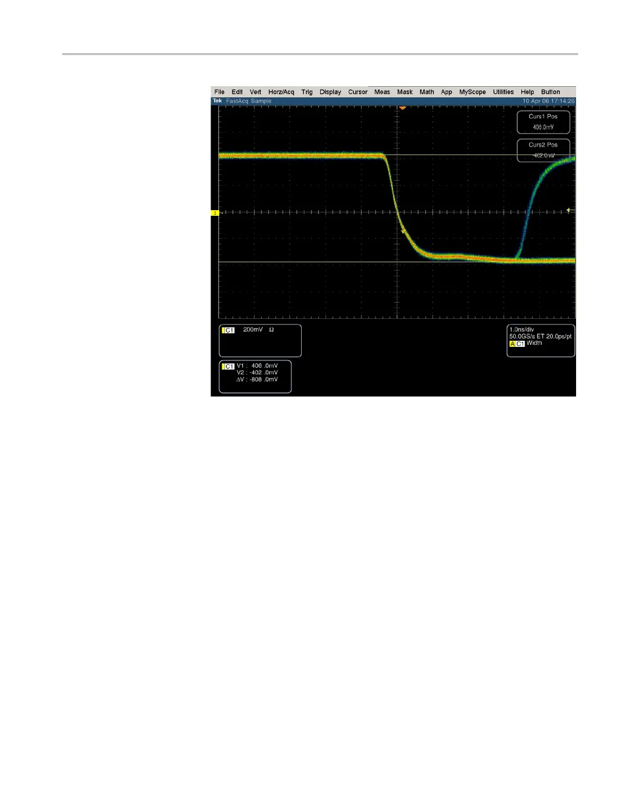
8. Set the oscilloscope cursor 2 to the bottom of the displayed waveform. (See
Figure 5.)
9. Record the amplitude (∆V) in the test record.
Waveform Monitors Specifications and P erformance Verification 105
 Loading...


