Video and General Performance Verification Procedures
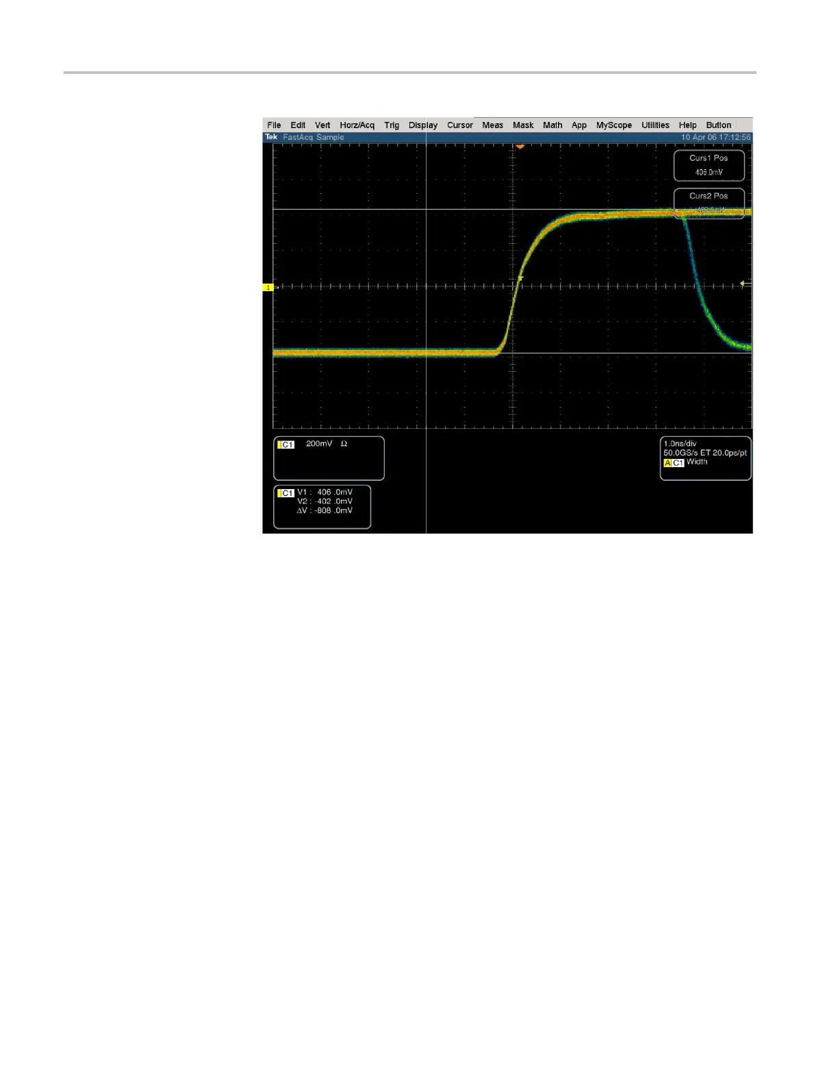
Figure 5: Trigger polarity negative
SD VITC Decoding
Functionality
Apply an SDI signal, that was converted from an NTSC signal, with VITC and
verify the VITC is correctly decoded.
1. Set the waveform monitor to the factory presets. (See page 60, Restore the
Factory Presets.)
2. Route the NTSC signal from the AVG1 to the VITC encoder.
3. Connect the output of the VITC encoder to the NTSC to SDI c onverter.
4. Con
nect the SDI from the converter the SDI A input of the DUT.
5. Set the waveform monitor for VITC timecode:
a. Press the CONFIG button.
b. Select AUX Data Settings.
c. Select Timecode Display Channel and then VITC.
d. Press CONFIG to remove the menu.
106 Waveform Monitors Specifications and Performance Verifi cation
 Loading...


