Video and General Performance Verification Procedures
Figur
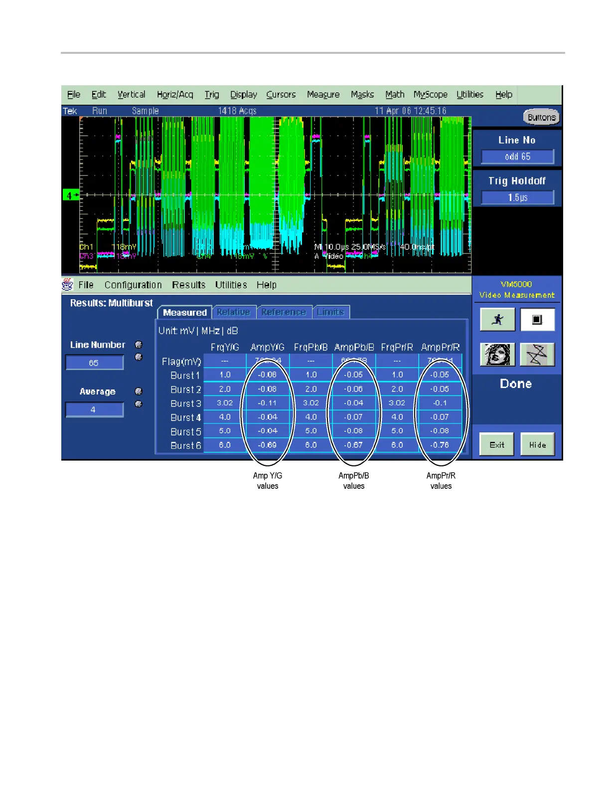
e 3: VM5000 SD Frequency Response display
11. Chec
k that the Burst dB values in the AmpY/G, AmpPb/B, and AmpPr/R
columns are between –0.92 dB (–10%) and +0.82 dB (+10%).
12. Rec
ord the results in the test record.
Analog Pixmon Gain and
Offset
This test uses an oscilloscope to check the active video gain and black (blanking)
levels at the Pixmon output, for the YPbPr, RGB, and C omposite modes.
1. Set the waveform monitor to the factory presets. (See page 60, Restore the
Factory Presets.)
2. Connect the TG2000 DVG1 output to the waveform monitor SDI A input.
Waveform Monitors Specifications and P erformance Verification 101
 Loading...


