Video and General Performance Verification Procedures
10. Check the wavef
orm. There should be no discontinuities or jagged edges. Use
the VERTICAL knob to view the entire waveform.
11. When the proce
ss is complete, press FULL to return to 4-tile view.
12. Press the Display Select 4 button to activate the lower-right tile.
13. When the c alibration process is complete, press the SEL button to turn off the
Eye Recovered Clock Test.
14. Press and hold the STATUS button and select Exit to exit calibration.
15. Record Pass or Fail in the test record.
LTC Decoding
Functionality
Apply an LTC signal and verify it is correctly decoded.
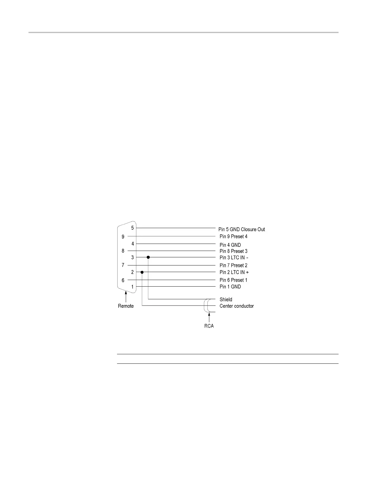
An LTC is i
nput through the 9-pin REMOTE connector on the rear panel. To input
an LTC signal, you need to construct a cable as shown in the following figure.
This cable has seven wires from the Remote connector, with two of them also
connectedtoanRCAconnector. Pin2oftheRemoteconnectorisconnectedto
the center pin of the RCA connector, and pin 3 is connected to the shield of the
RCA connector.
Figure 2: Wiring diagram for LTC input/Ground Closure cable
NOTE. Apply a signal to only one connector at a time.
1. Set the waveform monitor to the factory presets. (See page 60, Restore the
Factory Presets.)
2. Connect the RCA connector on the custom cable to the output of the Timecode
generator. Connect the custom cable 9-pin connector to the REMOTE
connector on the waveform monitor rear panel.
94 Waveform Monitors Specifications and Performance Verification

 Loading...


