20
Tempest900 2-Channel Operating Manual
4- Headset Connector
The 4-pin XLR male headset connector mates with most Dynamic or Electret headsets that have 4-pin XLR female connectors. This headset
connector allows a user to communicate in “Dual-listen” or “Single-listen” mode on either intercom channel.
The mic detect circuit (dynamic/electret) will indicate dynamic when it sees a load of 600Ω or less. It will indicate an electret when it sees 1kΩ or
greater. Between 600Ω and 1kΩ is not recommended as it may not accurately detect mic type.
Top
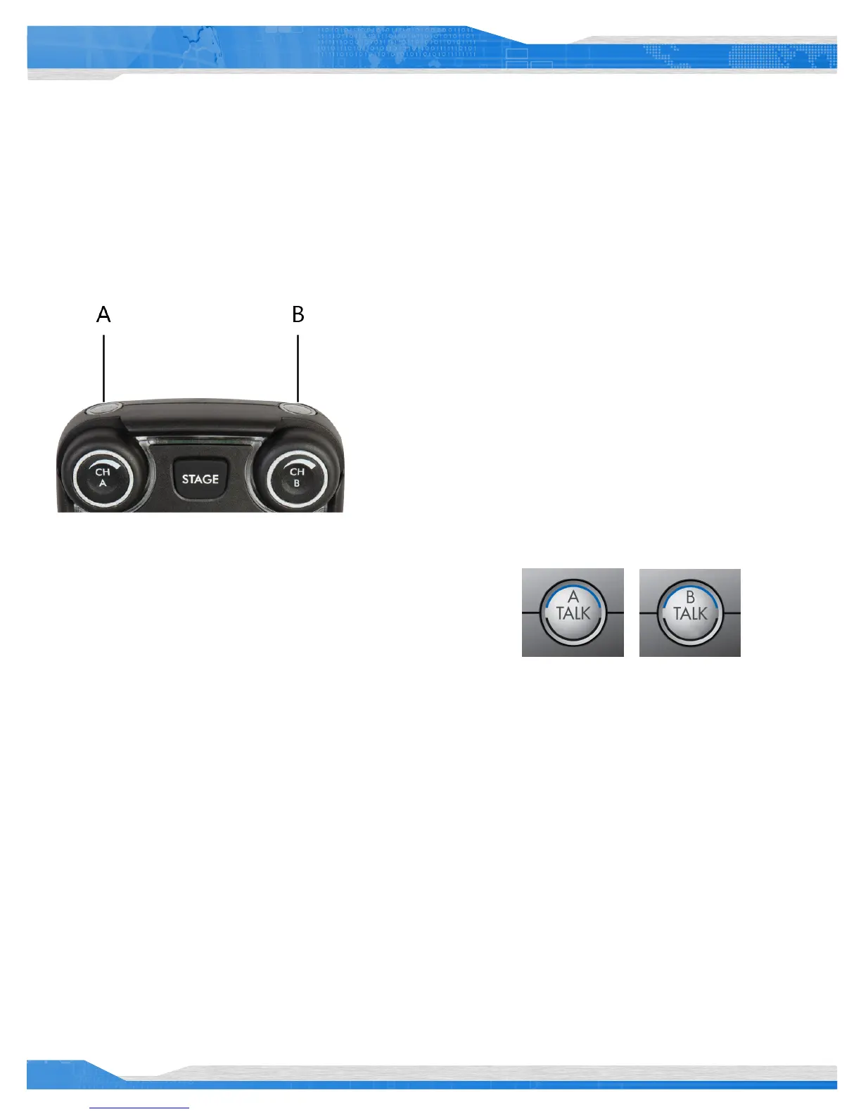
Talk Button A and B
There are two TALK buttons on each BeltStation, one for channel A and the
other for channel B. The Talk button enables the microphone signal for the
assigned intercom channels.
Tempest uses an intelligent latching method for TALK buttons. Pressing the
TALK button momentarily will cause the TALK button to latch. Pressing and
holding the TALK button will cause the button to act as a momentary switch.
Talk tones can be enabled or disabled per BeltStation. If enabled, users will
here a tone each time the TALK button is pressed.
Channel Indicator LEDs A and B
Each Talk button has two individual LED indicators. Together they surround the Talk
button. The LEDs will ash blue to indicate which intercom channel, A or B, has been
selected and will illuminate continuously to indicate that “Talk” is enabled on that
channel.
The Channel Indicator LEDs will ash red when the microphone signal is reaching a
peak level and is entering into limiting.