5-9
5
Accessories
LRC
Y
M
“OFF”
at
spring
charged
“OFF”
at
locked
E
MP2MP1
SOURCE
On
ON
Switch
E- E-
OFF
Switch
Off
“ON”
at
spring
charged
“ON”
at
spring
charged
“OFF”
at
spring
charged
“OFF”
at
MCCB:
ONorTRIP
Position
“ON”
at
MCCB:
ONorTRIP
Position
Yc
Yc
YaYa
Xb
Xb
Xa
X
LS HS
LS
(RESET)
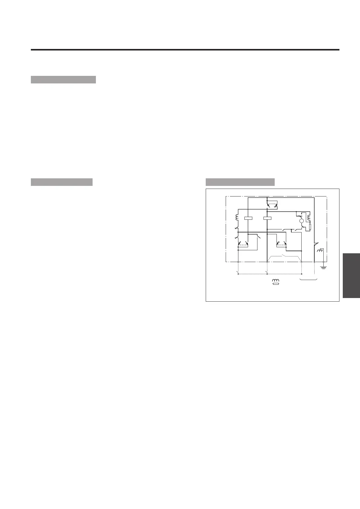
X: Anti-pumping relay
Y: Motor drive relay
LRC: Latch release coil (closing coil)
M: Motor
HS: Handle switch
: Field coil
: Resistor
+–
AUTO RESET
SWITCH
(OPTION)
Control circuit diagram
Operation mechanism
Motorized operation
■Breaker ON
Closing the ON switch activates the latch release coil (LRC), thereby releasing the closing spring to turn the breaker ON.
■Breaker OFF (RESET)
Closing the OFF/RESET switch activates the (Y) control relay, thereby starting the motor to turn the breaker OFF. At the same time, the closing
spring is charged. The motor is deenergized when the breaker turns OFF (RESET).
■Breaker auto-reset (optional)
The auto-reset option uses an auto-reset switch (alarm switch) through which the closing spring is charged and the breaker is reset automatically
after the breaker trips open. This option both for XMD and T2MC will be factory wired.
Notes: 1. Installable alarm switch will be only 1 piece.
2. When the breaker is equipped with the auto-reset option, a signal self-hold circuit is required because the signal provided by the alarm switch is a pulse.
Manual operation *
■Breaker ON
.
OFF (RESET)
Pulling down the operating lever turns the breaker ON and OFF/REST
alternately.
The handle returns to the original position when released.
※With auto-charge/discharge feature:
When manual ON operation is performed while the control power is
applied, the handle switch (HS) operates to discharge the closing spring.
OFF operation causes the closing spring to be charged.
When manual ON or OFF operation is performed while the control power
is lost, and afterwards the control power is recovered, the closing spring is
discharged or charged in the same manner as described above.
When the auto-charge/discharge action is in progress, mechanical noises
will be heard. The noises however do not mean a failure.
Operation Precautions
• Ensure that the actual operation voltage ranges from 85% to 110% of the rated one.
• The currents shown are the maximum values at the maximum rated operational voltage.
• When conducting the dielectric withstand voltage test, apply voltage between the control terminal group and ground. Ensure that the test
voltage does not exceed AC 1500 V (AC 500 V if the rated operation voltage is DC 24 V).
• If the breaker is equipped with the UVT device, ensure that the UVT device is reset before providing a closing signal to the breaker.
• It takes up to three seconds to complete motorized OFF operation. If the breaker requires to be immediately opened from a remote location in
an emergency, add the SHT or UVT device to the breaker for remote electrical tripping.
• When a thermal-magnetic breaker is tripped by the thermal OCR, wait for a few minutes; then reset the breaker.
• Make sure that the current and switching capacities of the operation switch are appropriate for the application.
• Avoid repeated and continuous applications of the operation power supply to the motor operator.
• Use noise filters if the control power supply of the motor operator is shared by peripheral devices. Otherwise, power supply noise may cause
malfunction of the peripheral devices.
• Be sure to apply power to control power terminal MP1. If the breaker is turned ON or OFF manually without power applied to MP1, the auto
charge/discharge feature is disabled, and thus the motor operator will not be activated next time. In such a case, applying the rated operation
voltage between control power terminals MP1 and MP2 will enable the auto charge/discharge feature.


 To Next Page