Operations Manual United Kingdom 1-October-2013
TA9 & 10 Tier 4 Page 4 - 15
Description 4
1. Beacon
2. Mounting Stem
3. Switch
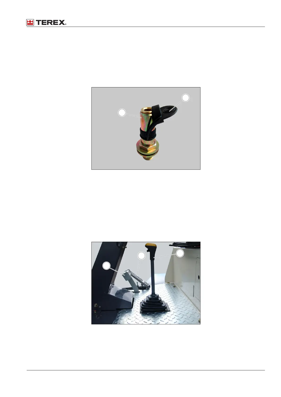
When the beacon is not required it can be removed and placed in its storage position within the
engine compartment to prevent theft or vandalism. When the beacon is removed from the ROPS
a rubber cover is fitted over the mounting stem to prevent the ingress of water.
Figure 4.15. - Mounting Stem
1. Mounting Stem
2. Rubber Cover
4.15 Foot Brake and Throttle Pedals
Refer to figure 4.16. The pedals are positioned in standard automotive format. The throttle pedal
controls the speed of the machine; the further the pedal is pressed down the faster the machine
will travel. To slow the machine and apply the brakes press the brake pedal.
Figure 4.16. - Driving Controls
1. Brake Pedal
2. Throttle Pedal
3. Gear Selector Lever
 Loading...