Appendix 9
TC29
85
9 Appendix
9.1 Electrical system
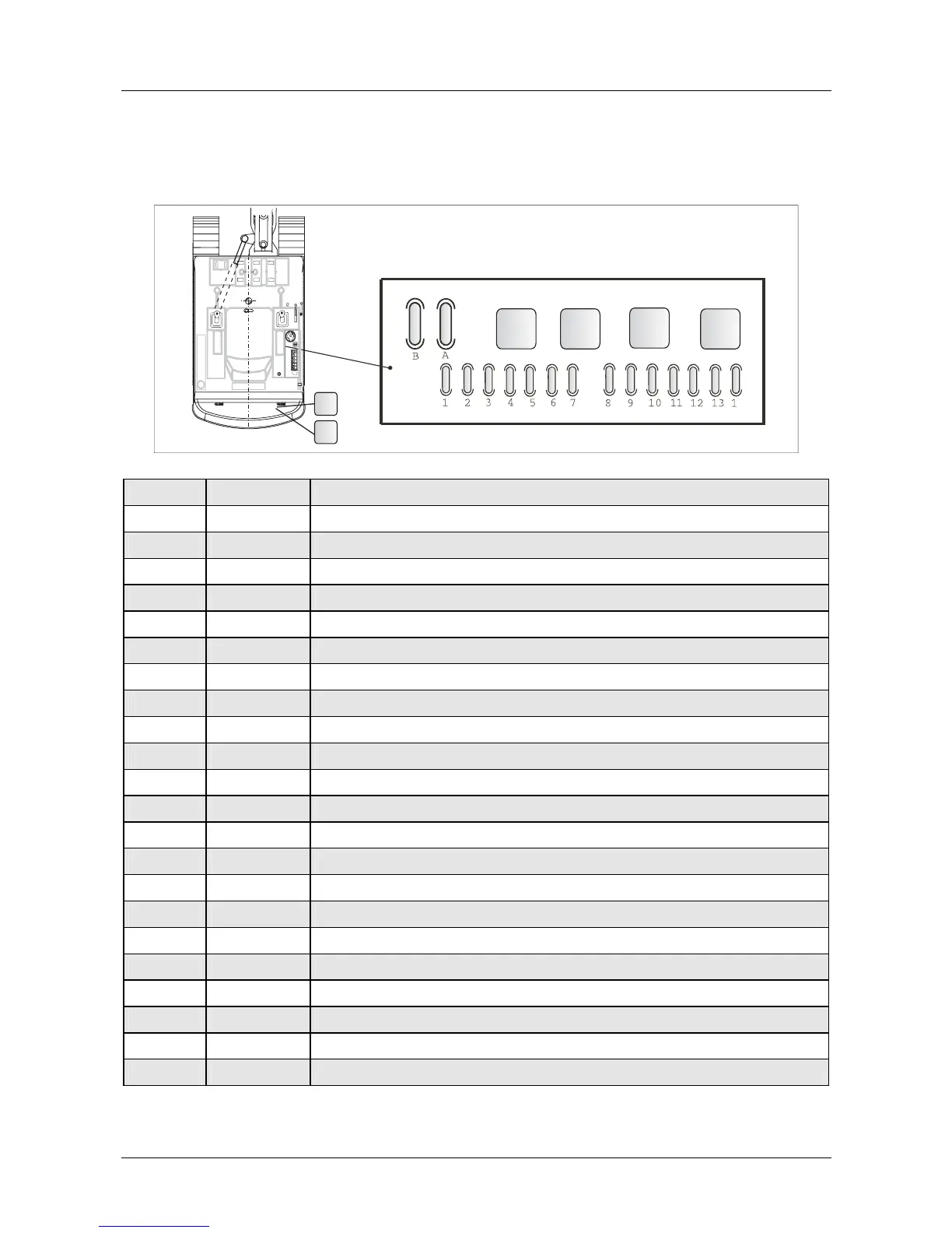
Fuse and relay box - Assignment diagram
4
K1
K2
K3
K4
TC29-35-48-04-E01
K10
K12
Position Amps Assigned to
FB 60 A Pre-heating fuse
FA 30 A Main fuse
F1 5 A
Instrument cluster 15, immobilizer
F2 10 A
Fuel pump, generator
F3 15 A Working floodlights, front
F4 15 A Working floodlights, rear; boom
F5 10 A Travel slow/fast, travel motion alarm
F6 10 A Swing brake, dozer blade
F7 15 A Heater fan
F8 15 A Windscreen washer
F9 10 A Horn, radio 15
F10 10 A
Option: 2nd control circuit, option: electrical seat
F11 5 A
Instrument cluster 30, immobilizer 30
F12 10 A
Interior light, radio 30, rotating beacon
F13 15 A Socket
F14 15 A
Option: refueling pump option: 30
K1 --
Main relay terminal 15
K2 --
Relay for swing brake
K3 --
Optional
K4 --
Optional
K10 --
Glow plug timing unit
K12 --
Time relay, engine shut-off
 Loading...