Appendix 9
TW85 113
9 Appendix
9.1 Electrical system
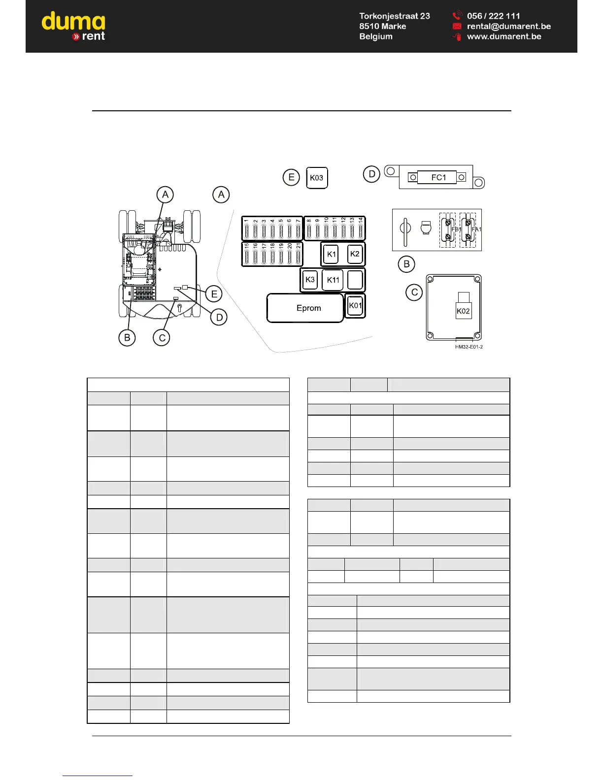
Fuse and relay box - Assignment diagram
A = Instrument panel B
= Maintenance
ascent
C
= Starter box
D = fuse E
= Power relay
Fuses
Position Ampere Assigned to
F 1 10 Interior light,
immobilizer, pre-heat
F 2 15 Socket, radio
auxiliary heating (option)
F 3 10 Warning blinker, flashing
signal, rotating beacon
F 4 15 Working floodlight, front
F 5 15 Working floodlight, rear
F 6 15 Refueling pump, electrical
seat (option)
F 7 10 Horn, switch illumination,
immobilizer
F 8 15 Heater fan
F 9 15 Windshield wiper and washer
system, radio
F10 5 Hydraulic oil level, overload
warning device, rock breaker,
auxiliary fitting
F11 5 Travel, parking brake, reverse
travel spotlight, brake light
switch
F12 5 Working hydraulics
F13 10 Brake light
F14 10 Warning blinker
F15 15 High beam light
F16 15 Low beam light
Fuses
Position Ampere Assigned to
F17 10
Side marker lamp, left,
instrument lights
F18 10 Side marker lamp, right
F19 10 Additional module
F20 10 Four-wheel steering (option)
F21 10 --
FA1 40 Main fuse terminal 30
FB1 40
Main fuse terminal 15,
starting relay
FC1 150 Fuse heating flange
Fuse colors
5A brown 10A red
15A blue 20A yellow
Relay
Position Function
K 01 Relay terminal 15
K 02 Starting relay
K 03 Preheat relay
K 1 Working floodlight, front
K 2 Working floodlight, rear
K 3
Not assigned (Air-conditioning -
option)
K11 Flasher transmitter