Installation Premier 24 Installation Manual
10 INS248
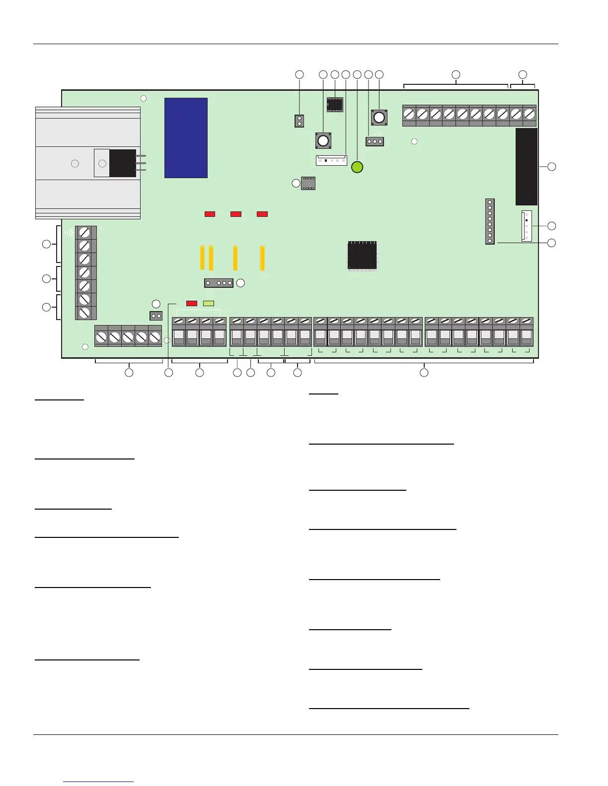
Control Panel PCB Layout
Com 1
Load Defaults
Panel Outputs
Spk
-
+Aux-
Tamper
Disable
Kick
Start
Engineer
Remote
Tx Rx
A.C.
+Batt-
12V
Aux Tamp
Bell Network Aux 12V
Com 2
Network
SK1
Digi Modem
Strb
0V Tamp Bell+12V
-
TR
+
Z1 Z2 Z3 Z4 Z5 Z6 Z7 Z8
F2
Fault
F3
Fault
F4
Fault
DC-DC+
Pg1
7 85 63 41 2 L/M R/R
Bell+12V
Enable
4
2
3
5
6
1
7 8 9 10
11
12
16
13
15
17
18
192021
23 22
24
26
25
14
1: AC Input
Connected to the 16.5V transformer.
"
DO NOT CONNECT THE MAINS SUPPLY TO THE AC
INPUT TERMINALS ON THE PCB.
2: Battery Connections
A 12V rechargeable battery must be connected to these
terminals in order to provide continuous system operation in
the event of an AC Mains failure (see page 12 for details).
3: Digicom Power
Unfused 12V power output for a stand alone communicator.
4: External Sounder Connections
These terminals are used for connecting to an external
sounder unit and is protected by a 900mA PTC – F2 (see
page 23 for wiring details).
5: Network Data Indicators
The red LED indicates that data is flowing out of the control
panel and normally flashes very quickly. The green LED
indicates that data is flowing into the control panel and
normally flashes slowly, the green LED flashes faster as
more devices are connected (see page 13 for details).
6: Network Connections
The Network provides connection for the keypads and zone
expander. The ‘+’ and ‘–’ terminals provide power
(protected by a 900mA PTC – F3) whilst the ‘T’ transmits
data and ‘R’ receives data (see page 13 for wiring details).
7: PG1
PG1 is a low current (100mA ‘-ve’ applied) output (see page
24 for wiring details). The output is also fully programmable
(see page 55 for programming details).
8: SPK- Loudspeaker Connection
These terminals can be used for connecting up to one 16Ω
or two 8Ω loudspeakers (see page 22 for wiring details).
9: Auxiliary 12V Power
These terminals are for connecting devices that require 12V
power (protected by a 900mA PTC - F4).
10: Auxiliary Tamper Connections
These terminals can be used for monitoring the box tamper
of auxiliary devices such as power supplies etc. (see page
21 for wiring details).
11: Programmable Zones 1 - 8
These terminals provide the connections for the 8 zones
(see page 21 for wiring details). Each zone is also fully
programmable (see page 34 for programming details).
12: Expansion Port
The expansion port is used for plugging on a local zone
expander (see page 17 for details).
13: Communication Port 2
Com Port 2 is a serial communications port and can be used
for connecting various devices.
14: Plug-on Digimodem Connections
This socket provides connection for a Com300, Com2400 or
ComISDN digimodem (see page 25 for details).

 Loading...


