CUTMASTER 60i
Manual 0-5475 SERVICE
5-15
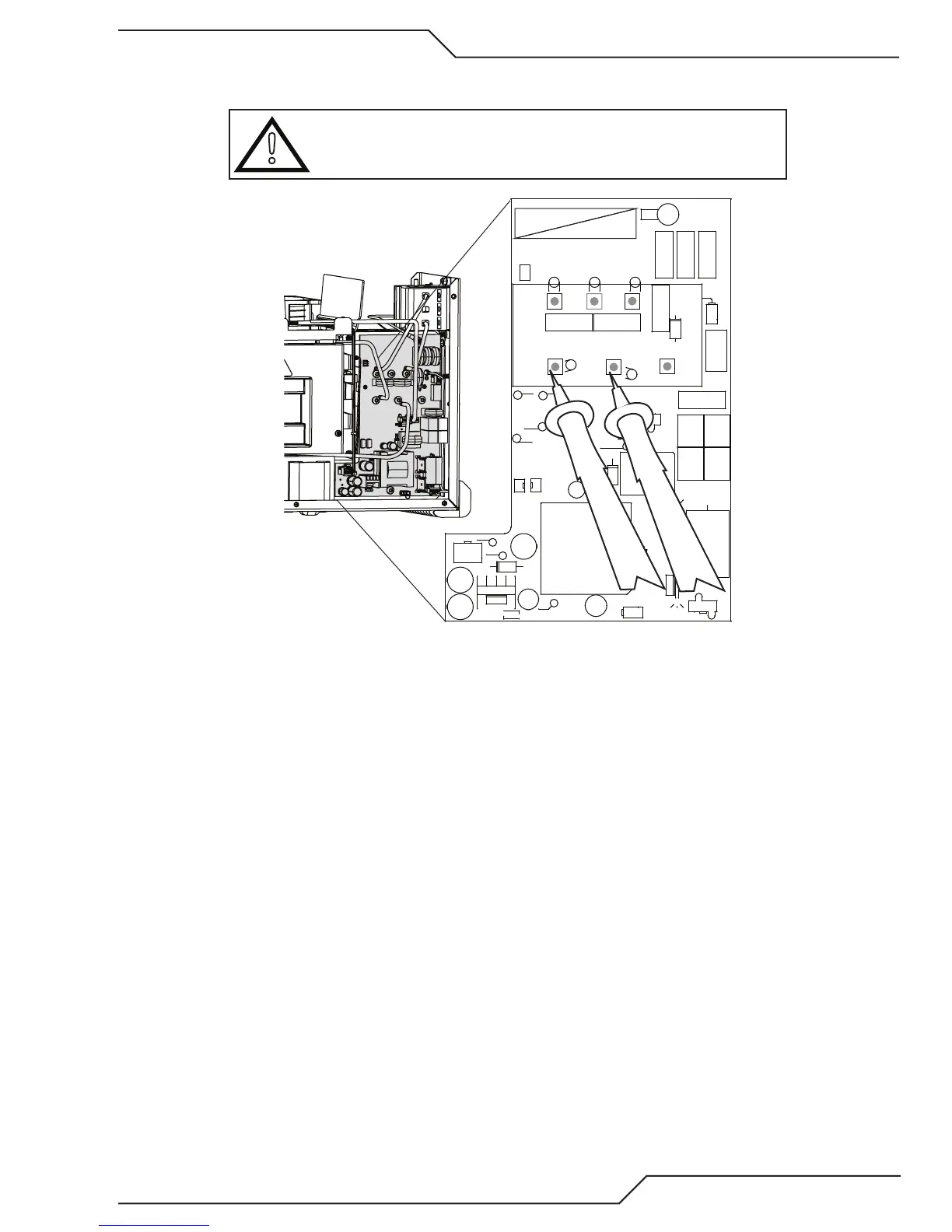
4. PFC Board IGBT Test. Measure between Bridge + to GND PRI (assumes PFC inductors L1 & L2 remain con-
nected.).
CAUTION
Single phase and 3 phase PFC boards are different, have different
catalog numbers! Using the wrong one may cause it to fail.
GRN/YEL
ORANGE
VIOLET
BLACK
ORANGE
BLACK
CHASSIS
GND
(3Ø ONLY)
+15V PRI
+24V
-15V
+15V
3Ø
1Ø
AC1
AC2
AC3
GND PRI
BRIDGE+
TP21
TP8 TP23
TP22
TP4
ACINSEN
HI LINE
BUS CHK
LO LINE15 UV
+
C303
D301
D303
HS300 HS301
C302
+
C300
C307
+
C306
+
C304
+
C301
D304
D306
D305
D307
1
J305
1
J304
46
13
J303
K300
MOV300 MOV301 MOV302
1
J302
Q301Q300
R300
R303
R301
R302
T300
1
U300
1
U301
+
C305
HS302
1
J301
D300
1
2
5
6
J300
T301
D302
MOV306
MOV304
MOV305
MOV303
E300
-
+
Art # A-13329
a. With meter on the diode scale place + meter lead on GND_PRI and – lead on BRIDGE +. It should read
as a diode in the forward direction with value similar to the PFC Diode, a little lower than the bridge
rectifier (step 2), (about 0.3V to 0.4V on Fluke meter.)
b. If reading is much lower (short) replace the PFC board.
c. If the reading is higher or slowly increasing, capacitor charging, you may have mixed up your + and –
meter leads. Reverse them and if the reading is still high, high in both directions, replace the PFC board.