CUTMASTER 60i
Manual 0-5475 SERVICE
5-17
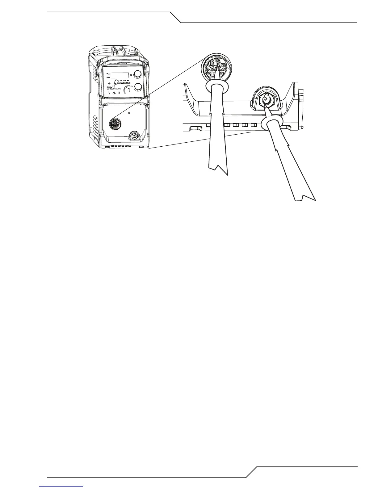
6. Inverter Board Output Diode Test. With the torch removed, measure Work to NEG at the front panel ATC
connector.
-
+
Art # A-13331
a. With meter on diode scale place the + lead on the negative terminal of the ATC connector and the – lead
on the Work lead Dinse receptacle.
b. The normal reading is that of a diode in the forward direction. (0.3V to 0.5V with Fluke.) If shorted replace
the Inverter board.
c. If above reads open, reverse the leads, you may have gotten + and – leads reversed.
d. If open in both directions check the connections from the work receptacle to the Inverter board stud la-
beled WORK. Also check for continuity from the ATC negative terminal to the SEC1 and SEC2 terminals
on the Inverter board. If these are OK replace the Inverter board