CUTMASTER 60i
SERVICE Manual 0-5475
5-18
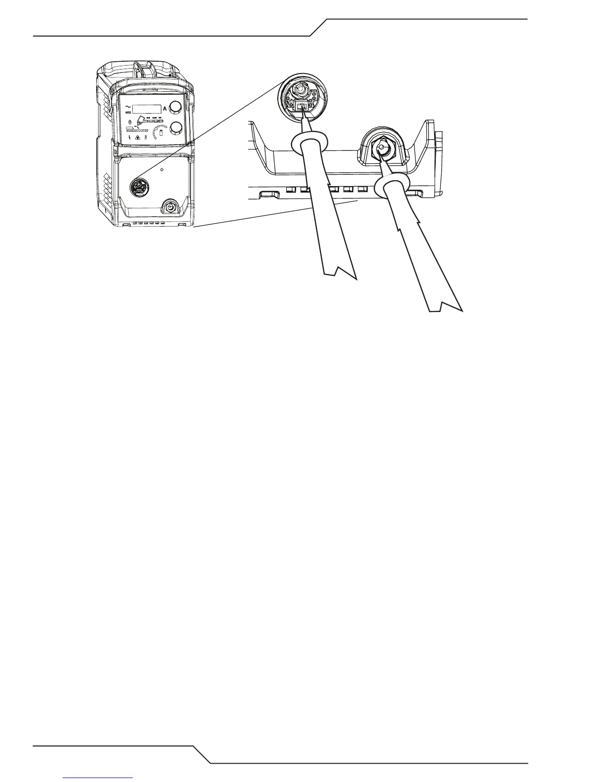
7. Inverter Board Pilot IGBT Test. Measure Tip to Work. (Torch removed from ATC) .
-
+
Art # A-13332
a. With meter on diode scale place the + lead on the pilot terminal of the ATC connector and the – lead on
the Work lead Dinse receptacle.
b. The normal reading is that of a diode in the forward direction. (0.3V to 0.5V with Fluke.) If shorted,
replace the Inverter board.
c. If above reads open, reverse the leads, you may have gotten + and – leads reversed. If open in both di-
rections check the connection from the ATC (red wire) to the Inverter board terminal labeled TIP. If OK
replace the Inverter board.