CUTMASTER 60i
SERVICE Manual 0-5475
5-44
Bias Supply PCB removal
WARNING
Disconnect primary power to the system
before disassembling the torch, leads, or
power supply.
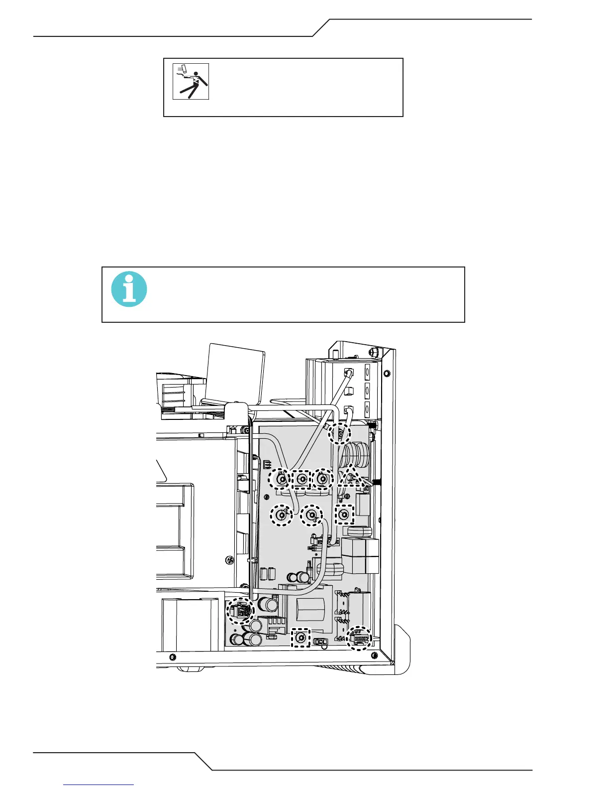
The Bias Supply PCB is located to the rear of the center chassis on the right side of the unit under the input power
switch. After the cover is removed it can be removed by following these steps.
1. Locate and identify each wire or harness attached to the Bias PCB for re-attachment later.
2. Disconnect each wire or harness at location indicated in the following illustration with a dotted line circle.
3. Disconnect the one jumper wire indicated with the dotted line triangle in the illustration below. DO NOT
LOSE it. This jumper will be used on the new PCB. .
4. Remove the remaining screws indicated by the dotted line squares in the illustration below. The Bias PCB
is now ready to remove.
NOTE!
DO NOT LOSE the plastic spacer behind the board at the bottom
screw. This will need to be replaced when reinstalling a new board.
Proedure is now complete.