CUTMASTER 60i
Manual 0-5475 SERVICE
5-45
PFC PCB removal
WARNING
Disconnect primary power to the system
before disassembling the torch, leads, or
power supply.
The PFC PCB is located on the right side of the system behind the air shroud. After the cover is removed it can
be removed by following these steps.
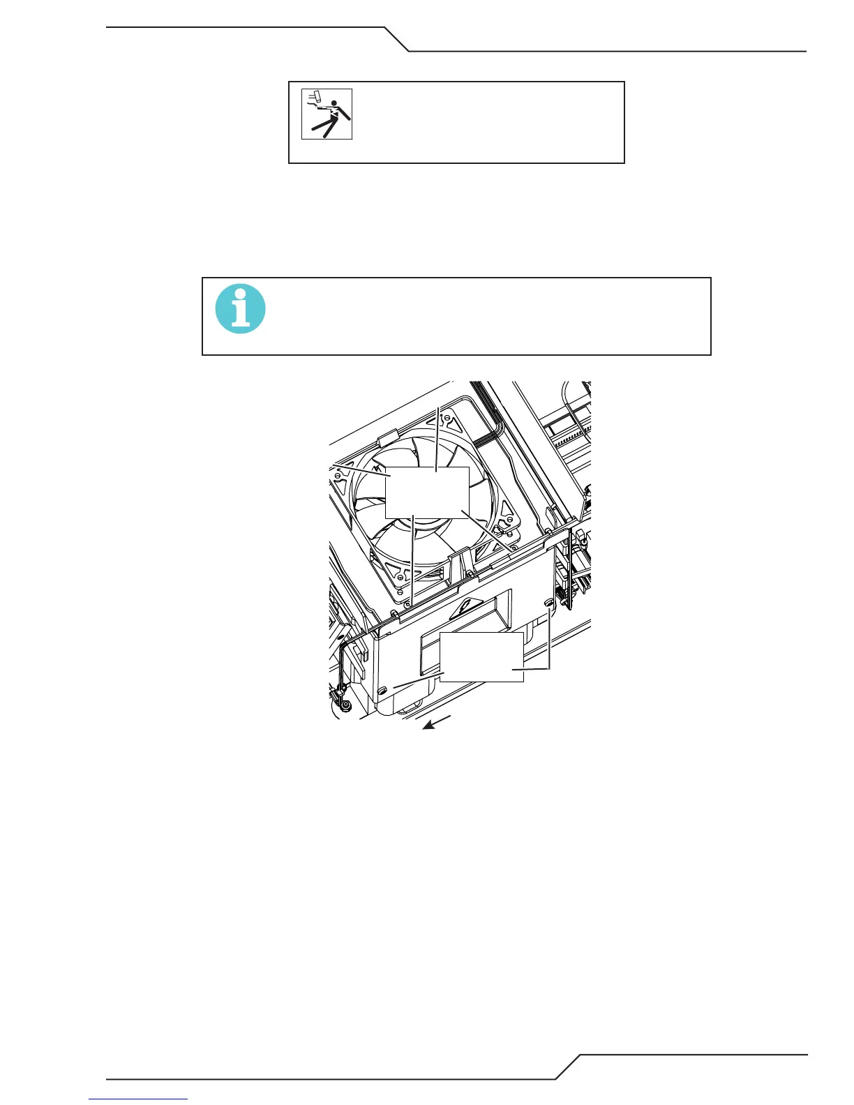
1. Remove the four T-15 Torx screws (6-19x1/2" trilobe) from the fan tray and the two Philips #1 nylon screws
holding the air shroud in place as seen in the following illustration.
NOTE!
DO NOT LOSE the nylon screws. The nylon screws must be used
when remounting the air shroud. DO NOT replace with metal
screws..
Two nylon
screws
Front of unit
Four screws
next to fan.
Art # A-13319