© 2016 Thorlabs
3 External Connections ITC8xxx
13
3.1.1 Connecting the Laser and Monitor Diodes
We recommend to use separate wires drilled in pairs (twisted pair) in a common shield for laser
diode current, monitor diode current and laser voltage measurement, respectively. The shield must
be connected to ground potential (pin 3).
If an external monitor diode is used, it must be connected with a coaxial cable with the outer
conductor to pin 2 and the inner conductor to pin 4.
Connect laser and monitor diode to the connector jack of the ITC8000 module.
The lines for voltage measurement of the laser diode (pin 6 and pin 9) must be connected as
closely as possible to the laser diode to avoid measurement errors.
The ground conductor of the monitor diode (pin 2) can be connected to the ground conductor of the
laser diode (pin 3). If this is necessary (e.g. laser diodes with integrated monitor diode and
common ground), connect the ground conductors as closely as possible to the laser diode to avoid
measurement errors when measuring the monitor diode current.
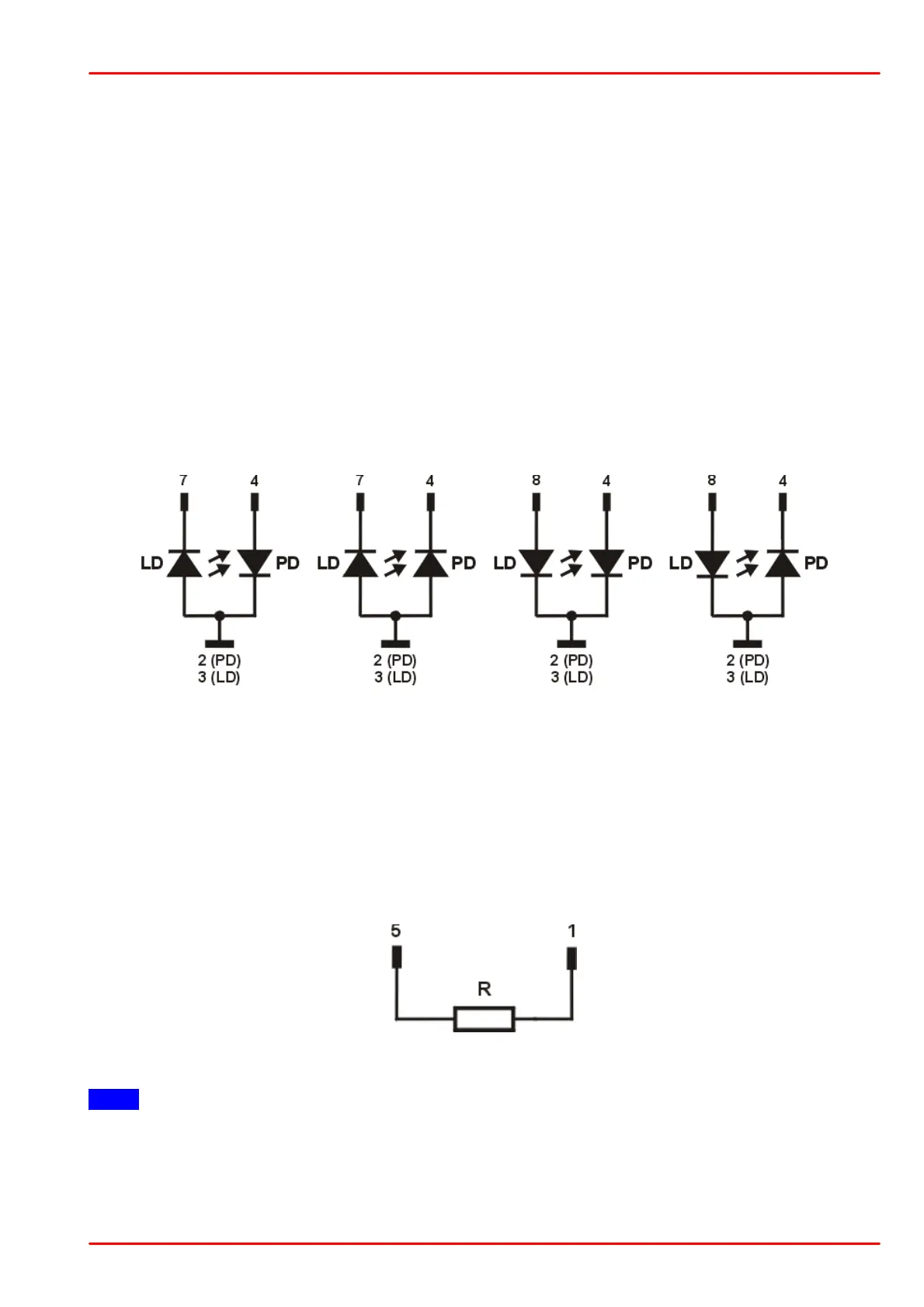
In this case the following pin assignments of the output jack are possible (shown without voltage
measurement):
LD - Laser Diode; PD - Photo (Monitor) Diode
3.1.2 Connecting Interlock and Status Display
Interlock and cable damage monitoring
The interlock function provides a safety feature in order to switch off instantly the laser. Therefore,
the connection between pin 1 and pin 5 of the connector jack serves as safety circuit:
· If the resistance between above mentioned pins is less than 430 W (short circuit allowed), the
laser current is enabled and can be switched on.
Note
Using a resistor > 430 W may lead to a malfunction as the status of the interlock is then in an
undefined range.
· In the case that the current between the interlock pins is interrupted, the laser controller cannot
be switched on. If this interruption happens during operation, the output will be switched off