FUNCTION CHARACTERISTICS
107
NVA100X-D - Manual - 02 - 2016
Logical block (Block1)
If the I2AL>BLK1 and/or I2>>BLK1 enabling parameters are set to ON and a binary input is
designed for logical block (Block1), the concerning element is blocked off whenever the given input
is active.
[1]
The enabling parameters are available inside the Set \ Profi le A(or B) \ Negative se-
quence overcurrent - 46G \ I2AL> Element (I2>> Element) menus, while the Block1 function must
be assigned to the selected binary input inside the Set \ Board1(2) inputs \ Binary input IN1-1...INx-x
menus.
All the parameters can be set separately for Profi le A and Profi le B.
Block3
The 46G element is disabled (with start of cooling timer) when:
the measured frequency becomes lower than 20 Hz or higher than 70 Hz or
all the phase voltages U
L1
, U
L2
, U
L3
are lower than 1% E
n
or
all the phase currents I
L1
, I
L2
, I
L3
are lower than 15% I
n
.
Note 1 The exhaustive treatment of the logical block (Block 1) function may be found in the “Logic Block” paragraph inside CONTROL AND MONITOR-
ING section
•
•
•
Fun-F46G_AL.ai
I
2
>≥ I
AL
>
&
RESET
t
2AL>def
0T
TRIPPING MATRIX
(LED+RELAYS)
I
2AL>def
t
2AL>def
I2AL> Start
I
2AL
>
ST-K
I
2AL
>
TR-K
I
2AL
>>
TR-L
I
2AL
>
ST-L
I
2AL
>
Start
I
2AL
>
Trip
I2AL> Trip
≥1
(ON≡
Inhibit
)
Block3
I2AL> Block1
I
2
I2>> Trip
=0 if 20≤f≤70 Hz
&
&
&
Enable (ON≡Enable)
Block1 input (ON≡Block)
Block1
Block1
Block1
Binary input INx
T0
Logic
INx
t
ON
INx
t
ON
INx
t
OFF
T0
n.o.
n.c.
INx
t
OFF
ON≡Enable I
AL
> element
I
2AL
>
Enable
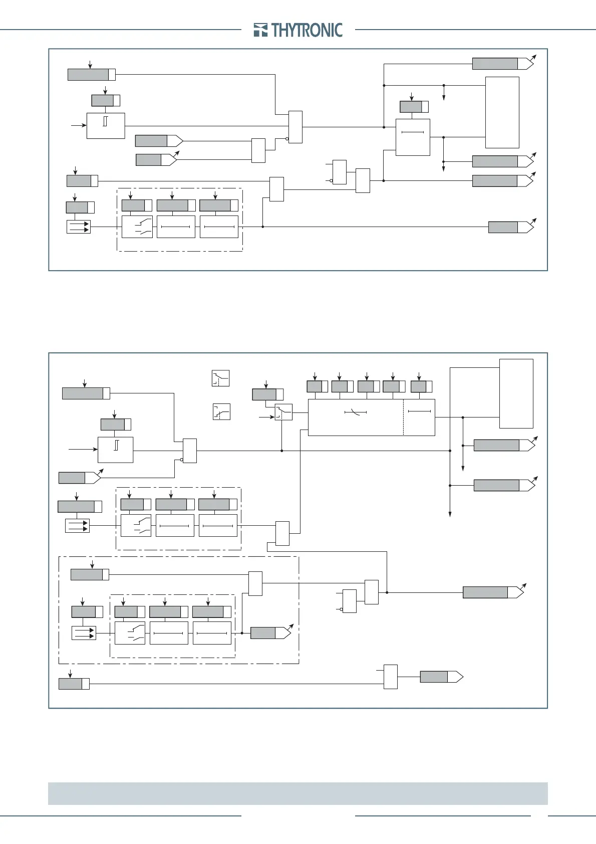
Logic diagram concerning the Alarm threshold of the negative sequence overcurrent element - 46G
Fun-F46G_S1.ai
I
2
≥ I
2
>
>
inv
&
≥1
TRIPPING MATRIX
(LED+RELAYS)
I
2
>
>
inv
I2>> Start
I2>> Start
I2>> Trip
Block3
I
2
I
2
=0 if 20≤f≤70 Hz
Reset LEDs
I2>> Start=OFF
I2>> Start=ON
I
2
>
>
inv
RESET
K
heat
t
2max
I
B
t
2min
0T
0T
K
cool
Binary input INx
T0
Logic
INx
t
ON
INx
t
ON
INx
t
OFF
T0
n.o.
n.c.
INx
t
OFF
I>>
ST-K
I>>
TR-K
I>>
TR-L
I>>
ST-L
ON≡Enable I
2
>> element
I
2
>>
Enable
BF Enable (ON≡Enable)
I2>>BF
I2>> BF
&
I2>> Trip
towards BF logic
Logic diagram concerning the trip threshold of the negative sequence overcurrent element - 46G
I2>> Start
I2>> Trip
I2>> Block1
Binary input INx
T0
Logic
INx
t
ON
INx
t
ON
INx
t
OFF
T0
n.o.
n.c.
INx
t
OFF
&
&
&
Enable (ON≡Enable)
I2>>BLK1
Block1
Block1
Block1
 Loading...


