280
NVA100X-D - Manual - 02 - 2016
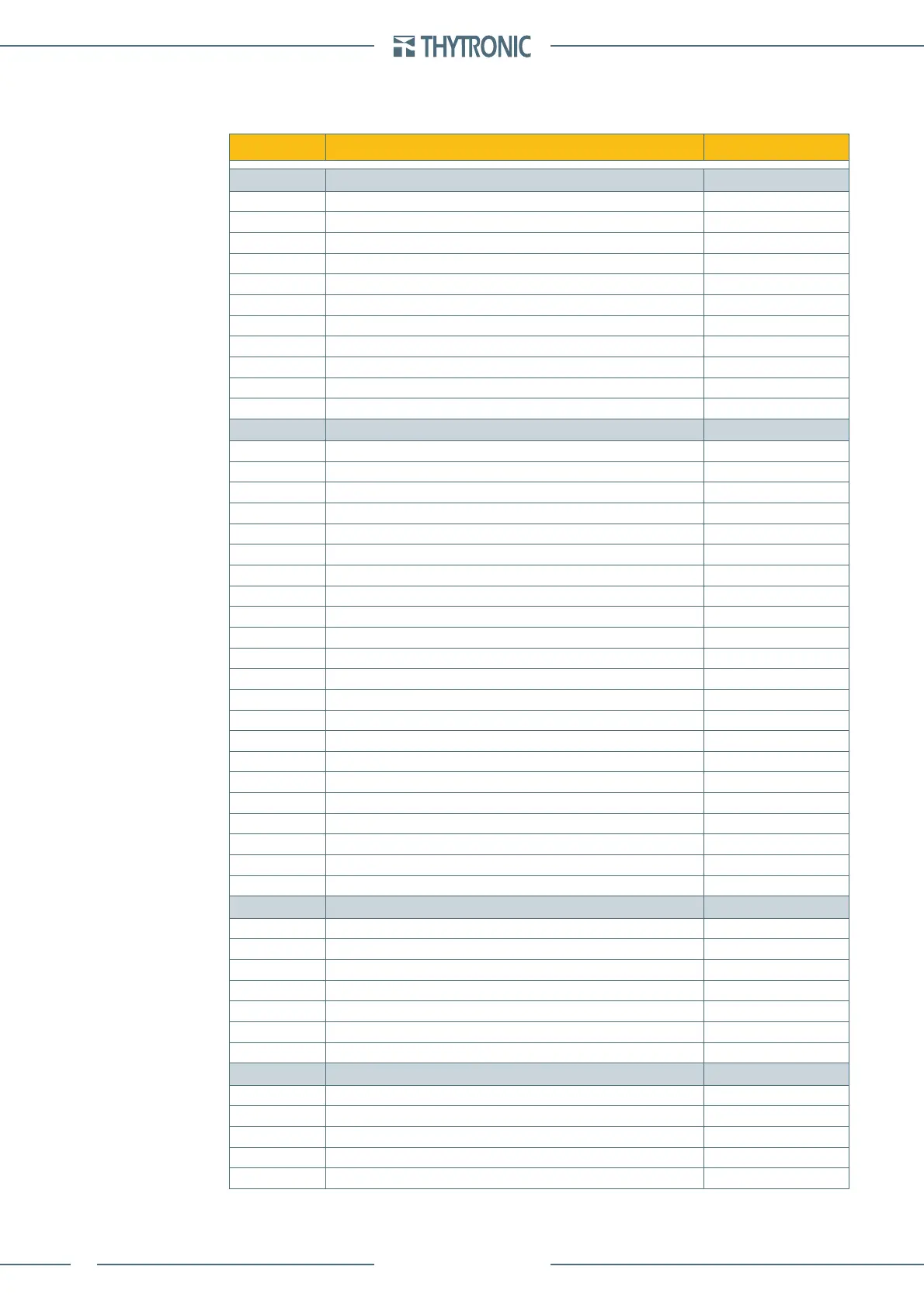
5 M E A S U R E S , L O G I C S T A T E S A N D C O U N T E R S
Measures
Measure Parameter Symbol
Direct
Lock frequency f
l
U
12
Phase-to-phase frequency f
U12
U
23
Phase-to-phase frequency f
U23
U
31
Phase-to-phase frequency f
U31
RMS value of fundamental component for phase currents side H I
L1H
, I
L2H
, I
L3H
RMS value of fundamental component for phase currents side L I
L1L
, I
L2L
, I
L3L
RMS value for phase currents side L I
L1L...3Lrms
RMS value of fundamental component for phase voltages U
L1
, U
L2
, U
L3
RMS value of fundamental component for residual current side 1 I
E1
RMS value of fundamental component for residual current side 2 I
E2
RMS value of fundamental component for residual voltage U
E
Calculated
Compensated currents side H I
L1cH
, I
L2cH
, I
L3cH
Compensated currents side L I
L1cL
, I
L2cL
, I
L3cL
Stabilization currents I
SL1
, I
SL2
, I
SL3
Differential currents I
DL1
, I
DL2
, I
DL3
Second harmonic of differential currents I
DL1-2nd
, I
DL2-2nd
, I
DL3-2nd
Fifth harmonic of differential currents I
DL1-5th
, I
DL2-5th
, I
DL3-5th
Thermal image DTheta
Phase-to-phase voltages U
12
, U
23
, U
31
Calculated residual voltage U
EC
Calculated residual current side H and side L I
ECH
, I
ECL
Maximum current between I
L1L
-I
L2L
-I
L3L
I
LmaxL
Minimum current between I
L1L
-I
L2L
-I
L3L
I
LminL
Average current between I
L1L
-I
L2L
-I
L3L
I
LL
RMS maximum current between I
L1Lrms
-I
L2Lrms
-I
L3Lrms
I
LmaxL-rms
RMS minimum current between I
L1Lrms
-I
L2Lrms
-I
L3Lrms
I
LminL-rms
RMS average current between I
L1Lrms
-I
L2Lrms
-I
L3Lrms
I
LL-rms
Maximum voltage between U
L1
-U
L2
-U
L3
U
Lmax
Minimum voltage between U
L1
-U
L2
-U
L3
U
Lmin
Average voltage between U
L1
-U
L2
-U
L3
U
L
Maximum voltage between U
12
-U
23
-U
31
U
max
Minimum voltage between U
12
-U
23
-U
31
U
min
Average voltage between U
12
-U
23
-U
31
U
Displacement
Displacement angle of I
L1
respect to U
L1
Phi
L1
Displacement angle of I
L2
respect to U
L2
Phi
L2
Displacement angle of I
L3
respect to U
L3
Phi
L3
Displacement angle of U
E
respect to I
E
Phi
E
Displacement angle of U
EC
respect to I
E
Phi
EC
Displacement angle of U
E
respect to I
EC
Phi
E-IEC(L/H)
Displacement angle of U
EC
respect to I
EC
Phi
EC-IEC(L/H)
Sequence
Positive sequence current side L I
1
Negative sequence current side L I
2
Negative sequence current/positive sequence current ratio side L I
2
/I
1
Positive sequence voltage U
1
Negative sequence voltage U
2
—
 Loading...


