42
NVA100X-D - Manual - 02 - 2016
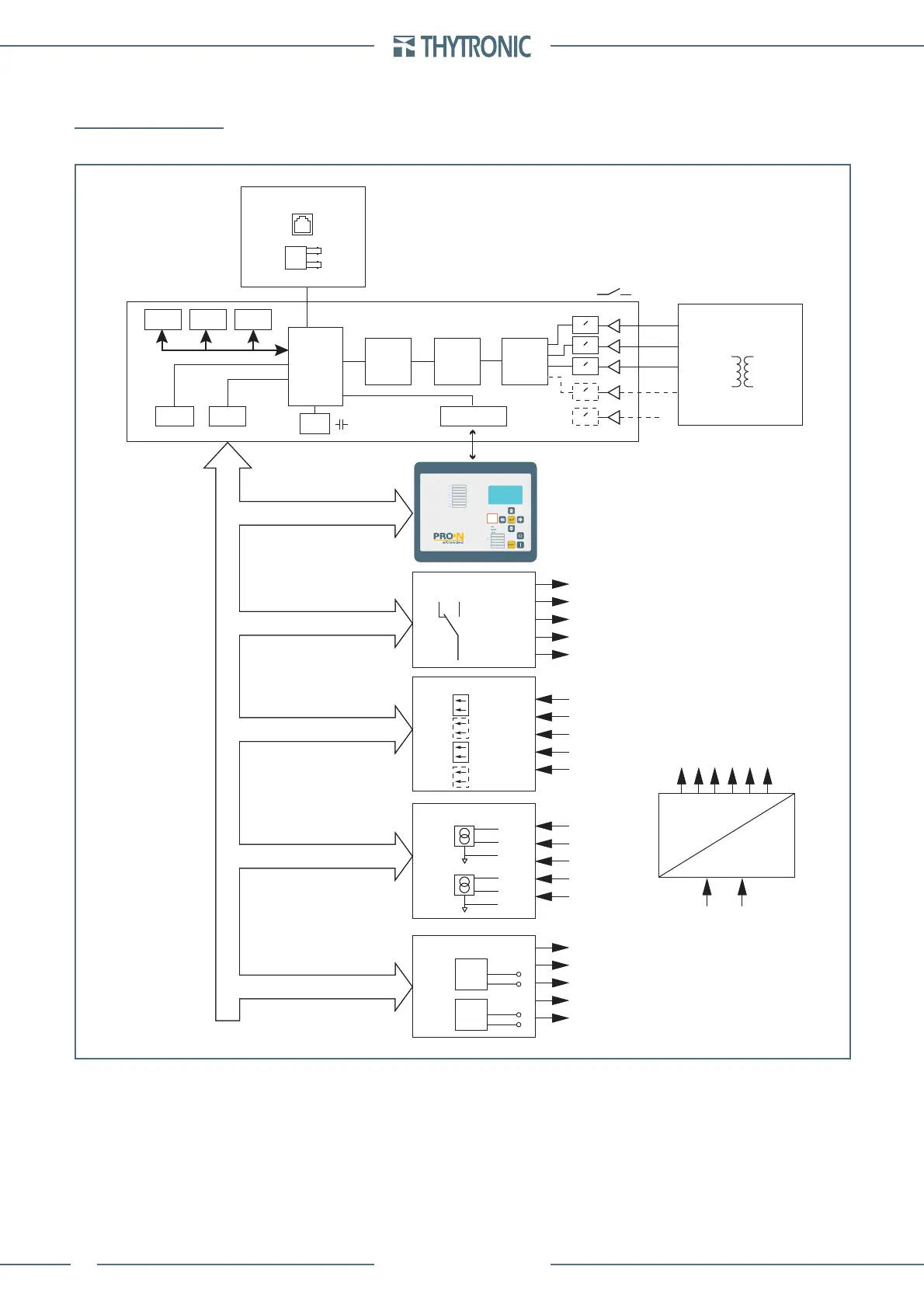
FUNCTION CHARACTERISTICS
4 FUNCTION CHARACTERISTICS
4.1 HARDWARE
Device layout
Power supply board
All the components necessary for conversion and stabilization functions are present.
Two versions are envisaged suited to the input ranges 24...48 V and 115...230 V.
The circuit provides stabilized voltages of +10 V and -10 V, required for the analogue measurement,
+24 V for relays and +5 V for supplying the digital circuits.
CPU module
This circuit board contains all the circuits necessary for performing the analogue and digital pro-
cessing of the signals.
—
—
hw.ai
RTC
EEprom Flash
ThybusRS485 RS232-Ethernet
SRam
CPU
ETHERNET
CPU
INPUT MODULE
CTs - VTs
OUTPUT RELAYS
DSP ADC
1A/5A
≈
≈
≈
≈
≈
KC1-1...KC1-8
KC2-1...KC2-8
Analog outputs
BINARY INPUTS
IN1-1
Uaux
IN1-16
IN2-16
IN2-1
Pt100
POWER SUPPLY
+3ю3 V
+10 V
0 V
+24 V
-10 V
+5 V
FPGA
PT1
MPT1
T1
PT8
MPT8
T8
MIS-1
-
+
# / ∩
MIS-4
-
+
# / ∩
 Loading...


