FUNCTION CHARACTERISTICS
215
NVA100X-D - Manual - 02 - 2016
Ground directional overcurrent with calculated residual current - 67N(Comp)
Preface
Four adjustable threshold with programmable operate time are available with characteristics similar
to the 67N protection described in the previous paragraph; the main difference is the residual cur-
rent that is vectorially calculated on the sides of H or L currents. The protection sensitivity is lower
compared to that obtainable with a direct measurement of the residual current from the balance
transformer.
All thresholds for residual current are expressed in pu of the nominal currents I
nH
(H side) and I
nL
(L side).
Operation and settings
Two operating mode may be selected by setting the Mode67N parameter, located inside the Set \
Profi le A(or B) \ Directional earth fault overcurrent-67N \ Common confi guration menu.
The settable operating modes are I (module) or I*cos (projection)
The fi rst and second threshold (I
EDC
>, I
EDC
>>) may be programmed with defi nite or inverse time ac-
cording the following characteristic curves:
Standard Inverse Time (IEC 255-3/BS142 type A or SIT): t = 0.14 · t
EDC
>
inv
/ [(I
EDC
/I
EDC
>
inv
)
0.02
- 1]
Very Inverse Time (IEC 255-3/BS142 type B or VIT): t = 13.5 · t
EDC
>
inv
/ [(I
EDC
/I
ECD
>
inv
) - 1]
Extremely Inverse Time (IEC 255-3/BS142 type C or EIT): t = 80 · t
EDC
>
inv
/ [(I
EDC
/I
EDC
>
inv
)
2
- 1]
Moderately Inverse (ANSI/IEEE type MI): t = t
EDC
>
inv
· {0.01 / [(I
EDC
/I
EDC
>
inv
)
0.02
- 1] + 0.023}
Very Inverse (ANSI/IEEE type VI): t = t
EDC
>
inv
· {3.922 / [(I
EDC
/I
EDC
>
inv
)
2
- 1] + 0.098}
Extremely Inverse (ANSI/IEEE type EI): t = t
EDC
>
inv
· {5.64 / [(I
EDC
/I
EDC
>
inv
)
2
- 1] + 0.024}
Electromechanical (EM): t = t
EDC
>
inv
· {0.28 / [-0236 · (I
EDC
/I
EDC
>
inv
)
-1
+ 0.339]}
Where:
t: operate time
I
EDC>inv,
I
EDC>>inv
: fi rst and second threshold setting
t
EDC
>
inv
, t
EDC
>>
inv
: fi rst and second threshold operate time setting
Third and fourth thresholds (I
EDC>>>def,
I
EDC>>>>def
) have defi nite time characteristic.
For all inverse time characteristics, following data applies:
Asymptotic reference value (minimum pickup value): 1.1 I
EDC
> or I
EDC
>>
Minimum operate time: 0.1 s
Range where the equation is valid:
[1]
1.1 ≤ I
EDC
/I
EDC
>
inv
(or I
EDC
>>
inv
) ≤ 20
If I
ED
>
inv
(or I
ED
>>
inv
) pickup ≥ 2.5 I
n
, the upper limit is 50 I
n
For all defi nite time elements the upper limit for measuring is 50 I
n
.
Note 1 When the input value is more than 20 times the set point , the operate time is limited to the value corresponding to 20 times the set point
—
•
•
•
•
•
•
•
•
•
•
•
•
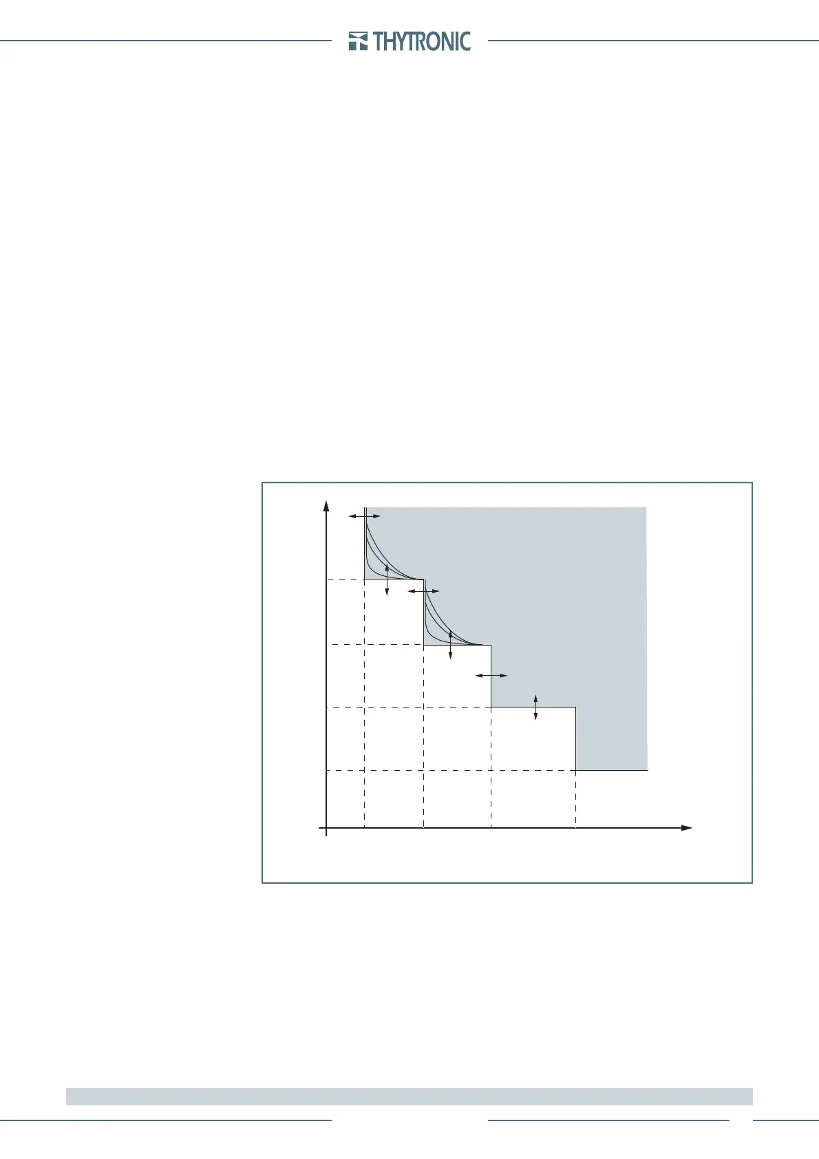
t-int-F67NC.ai
I
ECH or
I
ECL
I
EDC
>> I
EDC
>>> I
EDC
>>>>
t
EDC
>
t
EDC
>>
t
EDC
>>>
t
EDC
>>>>
I
EDC
>
t
General operation time characteristic for the ground directional overcurrent elements - 67N(Comp)
TRIP
 Loading...


