MEASURES, LOGIC STATES AND COUNTERS
285
NVA100X-D - Manual - 02 - 2016
Calculated residual voltage U
ECr
Displacement angle of I
L1(L)
respect to U
L1
Phi
L1Lr
Displacement angle of I
L2(L)
respect to U
L2
Phi
L2Lr
Displacement angle of I
L3(L)
respect to U
L3
Phi
L3Lr
Displacement angle of U
E
respect to I
E2
Phi
Er
Displacement angle of U
EC
respect to I
E2
Phi
ECr
Displacement angle of U
E
respect to I
ECL
/I
ECH
Phi
E-IEC(L/H)r
Displacement angle of U
EC
respect to I
ECL
/I
ECH
Phi
EC-IEC(L/H)r
Differential phase currents I
DL1r
, I
DL2r
, I
DL3r
Stabilization phase currents I
SL1r
, I
SL2r
, I
SL3r
Negative sequence current I
2r
Positive sequence voltage U
1r
Negative sequence voltage U
2r
Thermal image DTheta-
r
Total active power P
r
Total reactive power Q
r
Power factor CosPhi
r
Resistive component of the L1 phase impedance R
L1r
Reactive component of the L1 phase impedance X
L1r
Minimum impedance Z
minr
Number of starts N
Start-r
Real-time of starts T
Start-r
Input frequency U
12
f
U12r
Input frequency U
23
f
U23r
Input frequency U
31
f
U31r
Inputs IN1-1...IN1-16, IN2-1...IN2-16
Outputs KC1-1... KC1-8, KC2-1...KC2-8
Fault info
Event recording - SER
Recording is triggered by one or more causes:
Start and/or trip of any enabled protection or control element
Binary input activation (OFF-ON or ON-OFF transition)
Power-on or power-down (Auxiliary power supply)
Setting change.
Three hundred events are recorded into a circular FIFO (First In, First Out) buffer.
[2][1]
Following information are stored in every record:
Event counter
[2]
Date and time
Event cause (binary input/element trip/setting change)
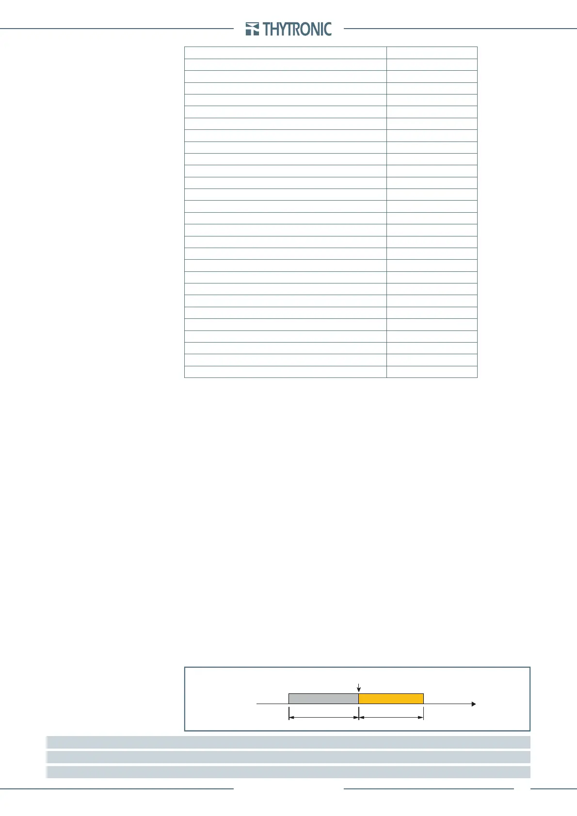
Oscillography - DFR
Upon programmable trigger, the fault records are recorded in COMTRADE format; the sampled mea-
sures (24 sample per cycle) are stored in a circular shift memory buffer.
The fault record are self-triggered; they are stored in sequential order up the allocated memory is
used up after which the oldest memory is overwritten. An operating procedure example for the digi-
tal fault recording is illustrated inside the ThySetter section.
Following parameters are user-programmable:
Pre-trigger and post-trigger time
Selected sampled quantities.
Analog channels (Analog 1...Analog 16) allocation.
Digital channels (Binary 1...Binary 16) allocation (output relay KC1-1...KC2-8 and/or binary inputs
IN1-1...IN2-16).
Digital channels (Binary 17...Binary 32) allocation for 87T state ((Id>-L1 ST....SatDet ST).
Trigger setup; the information storage starts when a state transition on the selected signal occurs.
(protective element start and/or trip, output relay and/or binary input switching).
Alarm: when the 80% of the buffer space is reached an alarm may be issued. The system being of
linear type, the records are back-to-back recorded to the end of available memory; the alarm out-
put is a warning in order that the user may download data
[3]
to clear memory for new records
Note 1 Event 0 is the newest event, while the Event 299 is the oldest event
Note 2 Counter is updated at any new record; it may be cleared by means ThySetter
Note 3 Data are stored into non-volatile memory; they are retained once power is turned off
—
•
•
•
•
•
•
•
—
•
•
•
•
•
•
•
Trigger
Time
pre-trigger post-trigger
Trigger
Time
pre-trigger post-trigger
 Loading...


