64
NVA100X-D - Manual - 02 - 2016
FUNCTION CHARACTERISTICS
Output relays
Eight or sixteen (one or two output boards) output relays are available (KC1-1...KC1-8, KC2-1...
KC2-8):
[1]
KC1-1, KC1-2, KC1-7, KC1-8, KC2-1, KC2-2, KC2-7, KC2-8 with two changeover contacts (SPDT, type C)
KC1-3, KC1-4, KC1-5, KC1-6, KC2-3, KC2-4, KC2-5, KC2-6 with one make contact (SPST-NO, type A).
Each output relay may be programmed with following operating mode:
Operation MODE (No latched, Pulse, Latched).
Logic (Energized/De-energized).
To each output relay a programmable timer is matched (Minimum pulse width parameter).
All parameters are available inside the Set \ Board 1(2) outputs menu.
Any change to the settings can be affected at any time, also with the relay on duty, separately for
each relay.
Notes:
When de-energized operating mode is set, the relay remains in rest condition if no trip command
is in progress.
When energized operating mode is set, the relay remains in operating condition if no trip command
is in progress and the auxiliary supply is powered on.
When no-latched operating mode is set (Operation MODE No latched), the output relay reset
at the end of the trip condition. To each output relay a programmable timer is matched (minimum
pulse width operation).
When latched operating mode is set (Operation MODE Latched), the output relay doesn’t reset
at the end of the trip condition; it stays ON until a reset command is issued (RESET key, ThySetter
or communication command).
When pulse operating mode is set (Operation MODE Pulse), the output relay reset after a t
TR
programmable delay regardless of the trip condition.
It is advisable to make sure that the output contact technical data are suitable for load (Nominal
current, breaking capacity, make current, switching voltage,...).
Matching every output relay to any protective element is freely programmable inside the Setpoints
submenus according a tripping matrix structure.
[2]
Note 1 Schematic diagram are shown inside APPENDIX B1.
Note 2 All features are listed; functions effectively present depend on the version
Matching of the output relay to the protective and control functions can be defi ned so that any collision from other function is avoided.
All output relay are unassigned in the default setting.
—
•
•
•
•
•
•
•
•
•
•
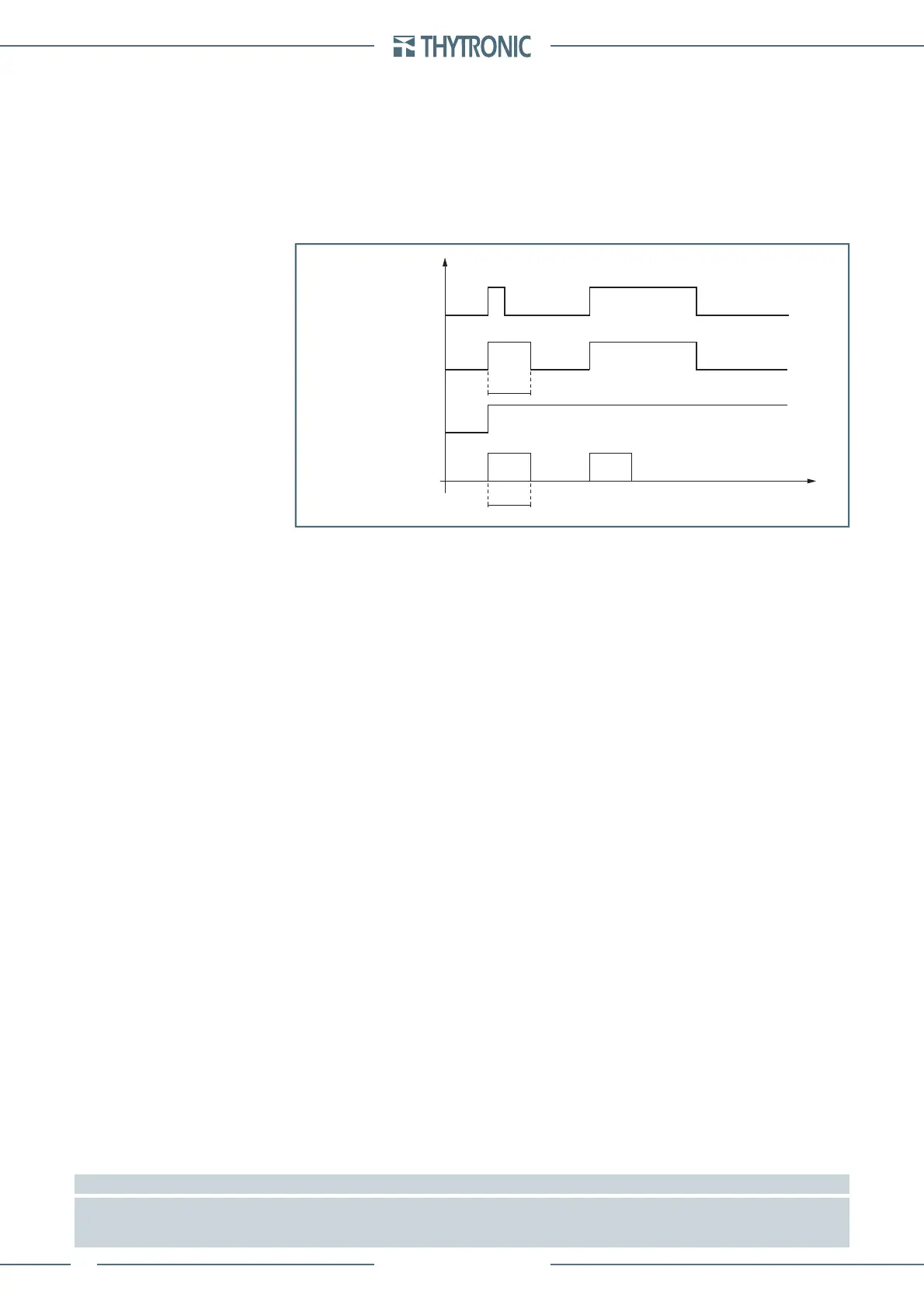
Input
No-latched operation
Latched operation
Pulse operation
Output relay operation
Minimum pulse width
Relay-operation-timers.ai
t
Minimum pulse width
t
TR
t
TR
Input
No-latched operation
Latched operation
Pulse operation
Output relay operation
Minimum pulse width
Relay-operation-timers.ai
t
Minimum pulse width
t
TR
t
TR
 Loading...


