FUNCTION CHARACTERISTICS
163
NVA100X-D - Manual - 02 - 2016
Residual overcurrent - 50N(Comp)/51N(Comp) side H or side L
[1]
Preface
The protection, which employs the residual current IEC measurement calculated vectorially from
the three phase currents, can be usefully employed in cases in which the residual current measured
directly is not available (for example when the core balance transformer in not available) or when
the high-impedance restricted earth fault differential protection is enabled.
Inside the Set \Profi le A(or B) \ Residual overcurrent 50N(Comp)/51N(Comp) / Common confi guration
menu, the side (L or H) where he residual current (IECH or IECL) is calculated can be selected.
Setting threshold are in p.u of phase rated current .
Operation and settings
The residual overcurrent protection compares the calculated critical component of residual current,
calculated as the sum of the instantaneous values of the phase currents on the selected side (H,
or L) with the setting thresholds (I
EC
>, I
EC
>>, I
EC
>>>). Current above the associated pickup value is
detected and a start is issued. After expiry of the associated operate time a trip command is issued;
if instead the current drops below the threshold, the element is restored. The fi rst threshold may be
programmed with defi nite or inverse time according the following characteristic curves
[2]
:
Standard Inverse Time (IEC 255-3/BS142 type A or SIT): t = 0.14 · t
EC
>
inv
/ [(I
EC
/I
EC
>
inv
)
0.02
- 1]
Very Inverse Time (IEC 255-3/BS142 type B or VIT): t = 13.5 · t
EC
>
inv
/ [(I
EC
/I
EC
>
inv
) - 1]
Very Inverse Time (IEC 255-3/BS142 type B or LIT): t = 120 · t
EC
>
inv
/ [(I
EC
/I
EC
>
inv
) - 1]
Extremely Inverse Time (IEC 255-3/BS142 type C or EIT): t = 80 · t
EC
>
inv
/ [(I
EC
/I
EC
>
inv
)
2
- 1]
Moderately Inverse (ANSI/IEEE type MI): t = t
EC
>
inv
· {0.01 / [(I
EC
/I
EC
>
inv
)
0.02
- 1] + 0.023}
Very Inverse (ANSI/IEEE type VI): t = t
EC
>
inv
· {3.922 / [(I
EC
/I
EC
>
inv
)
2
- 1] + 0.098}
Extremely Inverse (ANSI/IEEE type EI): t = t
EC
>
inv
· {5.64 / [(I
EC
/I
EC
>
inv
)
2
- 1] + 0.024}
Electromechanical (EM): t = t
EC
>
inv
· {0.28 / [-0236 · (I
EC
/I
EC
>
inv
)
-1
+ 0.339]}
where:
t: operate time
I
EC
: calculated residual current (I
ECH
for side H, I
ECL
for side L)
t
EC
>
inv
: pickup value
t
EC
>
inv
: operate time setting
For all inverse time characteristics, following data applies:
Asymptotic reference value (minimum pickup value): 1.1 I
EC
>
inv
Minimum operate time: 0.1 s
Range where the equation is valid:
[3]
1.1 ≤ I
EC
/I
EC)
>
inv
≤ 20
If I
EC
>
inv
≥ 2.5 I
n(H,L)
., the upper limit is 50 I
n(H,L)
For all defi nite time elements the upper limit for measuring is 50 I
n(H,L)
All residual elements can be enabled or disabled by setting ON or OFF the IEC> Enable, IEC>>
Enable e/o IEC>>> Enable parameters inside the Set \ Profi le A(or B) \ Calculated residual over-
current-50N(Comp)/51N(Comp) \ IEC> Element (IEC>> Element, IEC>>> Element) \ Setpoints menus.
The fi rst overcurrent element can be programmed with defi nite or inverse time characteristic by
setting the IEC>Curve parameter (DEFINITE, IEC/BS A, IEC/BS B, IEC/BS C, ANSI/IEE MI,
ANSI/IEE VI, ANSI/IEE EI, EM) available inside the Set \ Profi le A(or B) \ Calculated residual
overcurrent-50N(Comp)/51N(Comp) \ IEC> Element \ Setpoints menus.
The trip of IEC> element may be inhibited by the start of the second and/or third element (IEC>>, IE(H)>>>)
by setting ON the Disable IEC> by start IEC>>, Disable IEC> by start IEC>>> (IEC>disbyIEC>>,
IEC>disbyIEC>>>) parameters available inside the Set \ Profi le A(or B) \ Calculated residual
overcurrent-50N(Comp)/51N(Comp) \ IEC>>(IEC>>>) Element \ Setpoints menus.
Similarly the trip of the IE(H)>> element may be inhibited by start of the third element (IE(H)>>>) by
Note 1 Inside diagrams and text the IEC is the current residual current calculated by the vector sum of the currents of the selected side (the H or L side)
Note 2 The formulas concern to the 50N.1/51N.1 protection on the side 1 and similarly for formulas of to the 50N.2/51N.2 protection on the side 2
Note 3 When the input value is more than 20 times the set point , the operate time is limited to the value corresponding to 20 times the set point
—
•
•
•
•
•
•
•
•
•
•
•
•
•
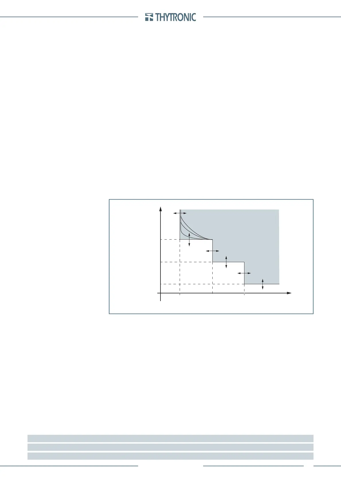
General operation time characteristic for the calculated residual overcurrent elements
I
EC
>>>
def
I
EC
t
EC
>
def -
t
EC
>
inv
I
EC
>
def
I
EC
>
inv
I
EC
>>
def
t
EC
>>
def
t
EC
>>>
def
t
TRIP
 Loading...


