FUNCTION CHARACTERISTICS
57
NVA100X-D - Manual - 02 - 2016
Binary inputs
Sixteen or thirty-two binary inputs are available (one or two input boards).
The dry inputs must be powered with an external voltage, (usually the auxiliary power supply).
The connections are shown in the schematic diagrams.
The following settings can be used to confi gure each input inside the Set \ Board 1(2) inputs \ Binary
input IN1-1...(IN1-x):
Logic Active-ON (activated when powered), or Active-OFF (activated when power is turned off).
ON Timer (OFF-to-ON time delay) and OFF Timer (ON-to-OFF time delay).
Binary input allocation.
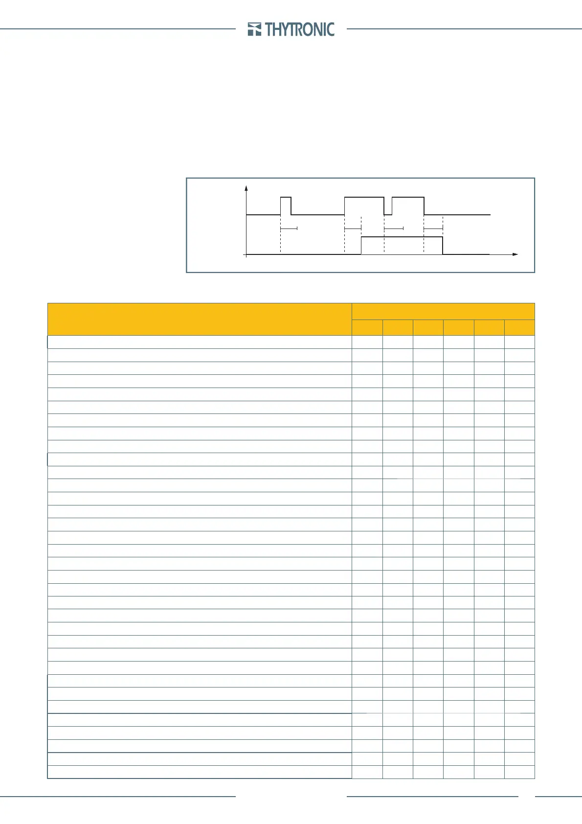
Adjustable debounce timer allows any transient to decay avoiding false activation of the input; the
positive transition is acquired if the input is permanently high for a time interval longer than the t
ON
setting delay; similarly for the negative transitions, the negative transition is acquired if the input is
permanently high for a time interval longer than the t
OFF
setting delay.
In the diagram, INTERNAL STATE represents the logical state of the binary input used in the following
processing. Each binary input may be matched to one of the following default functions.
ELEMENTS
Binary inputs
IN1-1 IN1-x IN1-16 IN2-1 IN2-x IN2-16
Reset LEDs
gggggg
Set profile (switching setting A and B)
gggggg
Fault trigger (fault recording)
gggggg
Block2 IPh/IE (selective block from phase and/or ground elements)
gggggg
Block2 IPh (selective block from phase elements)
gggggg
Block2 IE (selective block from ground elements)
gggggg
Block1 (logic block) side H-L
gggggg
Block1 (logic block) side H
gggggg
Block1 (logic block) side L
gggggg
Block1 (logic block) 87GMT
gggggg
TCS1 (Trip Circuit Supervision)
gggggg
TCS2 (Trip Circuit Supervision)
gggggg
Trip ProtExt (trip from external protection relays)
gggggg
Reset counters
gggggg
Reset CB Monitor (clear CB monitoring data)
gggggg
52a (CB auxiliary contact)
gggggg
52b (CB auxiliary contact)
gggggg
Open CB
gggggg
Close CB
gggggg
Preset DTheta (thermal image preset)
gggggg
Remote trip
gggggg
MCB VT OPEN (MCB auxiliary contact or fuse)
gggggg
MCB VT2 OPEN (MCB V2 auxiliary contact or fuse)
gggggg
Reset on demand measures
gggggg
Reset energy measures
gggggg
74VT ext. (74VT from external protection relays)
gggggg
I(L)>Bk (Logic block of I> element-side L, active through virtual I/O)
gggggg
I(L)>>Bk (Logic block of I>> element-side L, active through virtual I/O)
gggggg
I(L)>>>Bk (Logic block of I>>> element-side L, active through virtual I/O)
gggggg
I(H)>Bk (Logic block of I> element-side H, active through virtual I/O)
gggggg
I(H)>>Bk (Logic block of I>> element-side H, active through virtual I/O)
gggggg
I(H)>>>Bk (Logic block of I>>> element-side H, active through virtual I/O)
gggggg
IE1>Bk (Logic block of IE1> element, active through virtual I/O)
gggggg
IE1>>Bk (Logic block of IE1>> element, active through virtual I/O)
gggggg
—
•
•
•
BINARY INPUT
INTERNAL STATE
t
ON
t
ON
t
OFF
t
OFF
t
binary-timers.ai
BINARY INPUT
INTERNAL STATE
t
ON
t
ON
t
OFF
t
OFF
t
binary-timers.ai
 Loading...


