FUNCTION CHARACTERISTICS
181
NVA100X-D - Manual - 02 - 2016
Residual overvoltage - 59N
Preface
Two operation thresholds, independently adjustable with adjustable delay.
The fi rst one (U
E
>) may be programmed with defi nite or inverse time, while the second threshold
operates with defi nite time characteristic.
Each threshold may be separately enabled or disabled.
The fi rst threshold trip may be inhibited by start of the second threshold.
Operation and settings
Two measuring criteria of the residual voltage are provided:
Direct
Calculated.
For direct measure the fundamental component of the residual voltage input is used (U
E
), whereas,
for calculated measure (U
EC
) the residual voltage comes from a vector sum of three phase voltage
phasors.
The residual voltage (U
E
or U
EC
) is compared with the setting values (U
E
>, U
E
>>); a start is issued
when the residual voltage overcomes the adjustable threshold (START); after expiry of the associ-
ated operate time (t
UE
>, t
UE
>>) a trip command is issued; if instead the voltage drops below the
threshold, the element is restored.
The fi rst threshold (U
E
>) may be programmed with defi nite or inverse time according the following
characteristic curve:
t=0.5 t
UE
> / [(U
E
/U
E
>
inv
) - 1] (direct meaure of U
E
for VTs input versions) or
t=0.5 t
UE
> / [(U
EC
/U
E
>
inv
) - 1] (calculated measure of U
EC
for VTs input versions or ThySensor)
where:
U
E
: measured residual voltage
U
EC
: calculated residual voltage
t: operate time
U
E
>
inv
: threshold setting
t
UE>inv
: operate time setting
For the inverse time characteristic, following data applies:
The operate time setting is referred to an input voltage equal to 1.5 of the pickup value.
Asymptotic reference value (minimum pickup value): 1.1 U
E
>
inv
Minimum operate time: 0.1 s
Range where the equation is valid: 1.1 ≤ U
E
/U
E
>
inv
≤ 4
If U
E
>
inv
pickup ≥ 0.5 U
En
, the upper limit is 2 U
En
.
The fi rst residual overvoltage element can be programmed with defi nite or inverse time character-
istic by setting the UE> Curve parameter (DEFINITE, INVERSE) available inside the Set \ Profi le
A(or B) \ Residual overvoltage-59N \ UE> Element \ Setpoints menu.
Each element can be enabled or disabled by setting ON or OFF the UE> Enable parameter inside
the Set \ Profi le A(or B) \ Residual overvoltage-59N \ UE> Element \ Setpoints menu and/or the State
parameter inside the Set \ Profi le A(or B) \ Residual overvoltage-59N \ UE>> Element \ Defi nite time.
Selection of the measuring criteria of the residual voltage (direct measure or calculated measure) is
available inside the Set \ Profi le A(or B) \ Residual overvoltage-59N \ Common confi guration menu;
The 3Votype59N parameter may be select as UE (direct measure) or UEC (calculated measure).
—
•
•
•
•
•
•
•
U
EC
=|U
L1
+U
L2
+U
L3
|
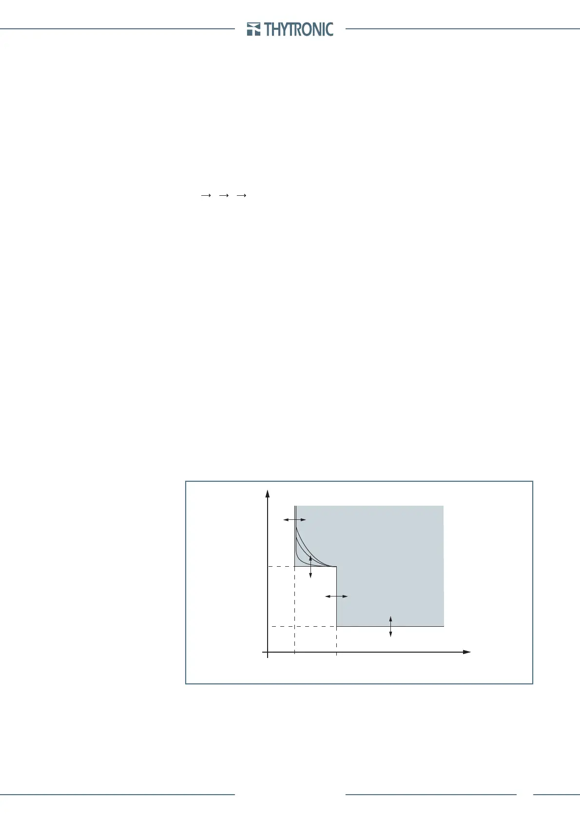
t-int-F59N.ai
U
E
U
E
>>
t
UE
>
t
UE
>>
U
E
>
t
TRIP
General operation time characteristic for the residual overvoltage elements - 59N
 Loading...


