FUNCTION CHARACTERISTICS
185
NVA100X-D - Manual - 02 - 2016
Negative sequence overvoltage - 59V2
Preface
The element has an adjustable threshold with time defi nite delay.
Enabling or disabling may be performed through ThySette.
Operation and settings
The negative sequence voltage is calculated as:
U
2
=(U
L1
+e
-j120°
·U
L2
+e
+j120°
·U
L3
)/3
where e
-j120°
=-1/2-j√3/2, e
j120°
=-1/2+j√3/2.
The negative sequence voltage is compared with the setting value (U
2
>
def
).
Voltages above the associated pickup value are detected and a start is issued. After expiry of the
associated operate time (t
U12
>
def
) a trip command is issued; if instead the voltage drops below the
threshold, the element is restored.
The element can be enabled or disabled by setting ON or OFF the State parameter inside the Set \
Profi le A(or B) \ Negative sequence overvoltage-27V2 \ U2> Element \ Setpoints menu.
Breaker failure (BF)
The 59V2 element can produce the Breaker Failure output if the U2>BF parameter is set to ON.
The parameters are available inside the Set \ Profi le A(or B) \Negative sequence overvoltage-59V2
\ U2> Element \ Setpoints menu.
[1]
Logical block (Block1)
If the U2>BLK1 enabling parameter is set to ON and a binary input is designed for logical block
(Block1), the protection is blocked off whenever the given input is active.
The trip timer is held in reset condition, so the operate time counting starts when the input block goes
down.
[2]
The enabling parameters are available inside the Set \ Profi le A(or B) \Negative sequence
overvoltage-59V2 \ U2> Element \ Setpoints menu, while the Block1 function must be assigned to
the selected binary input inside the Set \ Board1(2) inputs \ Binary input IN1-1...INx-x) menus.
All the parameters can be set separately for Profi le A and Profi le B.
Note 1 The common settings concerning the Breaker failure protection are adjustable inside the Breaker Failure - BF menu.
Note 2 The exhaustive treatment of the logical block (Block 1) function may be found in the “Logic Block” paragraph inside CONTROL AND MONITOR-
ING section.
—
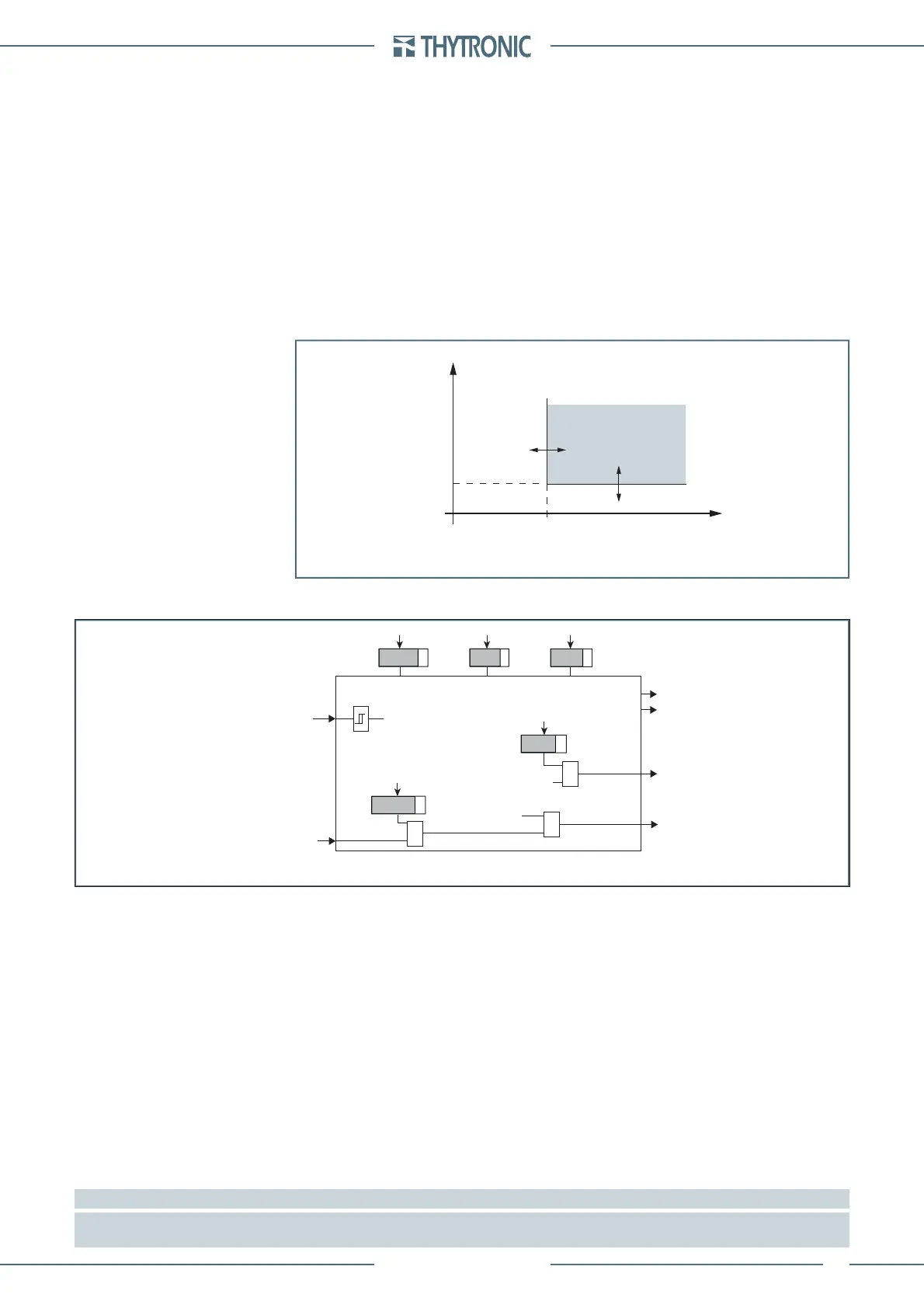
t-int-F59V2.ai
U
2
U
2
>
def
t
t
U2
>
def
General operation time characteristic for the positive overvoltage element - 59V2
TRIP
all-597V2.ai
General operation time characteristic for the positive overvoltage element - 59V2
U2> Element
Start U2>
Trip U2>
t
U2>
def
U
2
>
def
State
Block1
BLK1U2>
&
U2>BLK1
Start U2>
&
U2>BF
Trip U2>
&
U2>BF
U
2
 Loading...


